[Sammelthread] ASUS ROG Crosshair VI Hero
--- Produktseite | PDF-Handbuch (DE) | Support-Downloads | Preisvergleich ---


Spezifikationen
| CPU | AMD AM4 Socket for AMD Ryzen™/7th Generation A-series/Athlon™ Processors Supports AM4 Socket 14 nm CPU Supports CPU up to 8 cores * Refer to ASUS Deutschland for CPU support list |
| Chipset | AMD X370 |
| Memory | AMD Ryzen™ Processors 4 x DIMM, Max. 64GB, DDR4 3200(O.C.)/2666/2400/2133 MHz Non-ECC, Un-buffered Memory * AMD 7th Generation A-series/Athlon™ Processors 4 x DIMM, Max. 64GB, DDR4 2400/2133 MHz Non-ECC, Un-buffered Memory * Dual Channel Memory Architecture * Refer to ASUS Deutschland for the Memory QVL (Qualified Vendors Lists). |
| Multi-GPU Support | Supports NVIDIA® 2-Way SLI™ Technology *3 Supports AMD CrossFireX™ Technology |
| Expansion Slots | AMD Ryzen™ Processors 2 x PCIe 3.0/2.0 x16 (x16 or dual x8) AMD 7th Generation A-series/Athlon™ Processors 1 x PCIe 3.0/2.0 x16 (x8 mode) AMD X370 chipset 1 x PCIe 2.0 x16 (max at x4 mode) *1 3 x PCIe 2.0 x1 |
| Storage | AMD Ryzen™ Processors : 1 x M.2 Socket 3, with M key, type 2242/2260/2280/22110 storage devices support (SATA & PCIE 3.0 x 4 mode) AMD 7th Generation A-series/Athlon™ Processors : 1 x M.2 Socket 3, with M key, type 2242/2260/2280/22110 storage devices support (SATA mode) AMD X370 chipset : 8 x SATA 6Gb/s port(s), Support Raid 0, 1, 10 |
| LAN | Intel® I211-AT, 1 x Gigabit LAN Controller(s) Anti-surge LANGuard ROG GameFirst IV |
| Audio | ROG SupremeFX 8-Channel High Definition Audio CODEC S1220 - Impedance sense for front and rear headphone outputs - Supports : Jack-detection, Multi-streaming, Front Panel Jack-retasking - High quality 120 dB SNR stereo playback output and 113 dB SNR recording input - SupremeFX Shielding Technology - ESS® ES9023P - Supports up to 32-Bit/192kHz playback *2 Audio Feature : - Gold-plated jacks - Optical S/PDIF out port(s) at back panel - Sonic Radar III - Sonic Studio III |
| USB Ports | AMD Ryzen™/7th Generation A-series/Athlon™ Processors : 4 x USB 3.0 port(s) (4 at back panel, blue) AMD X370 chipset : 1 x USB 3.1 front panel connector port(s) AMD X370 chipset : 6 x USB 3.0 port(s) (4 at back panel, blue, 2 at mid-board) AMD X370 chipset : 6 x USB 2.0 port(s) (4 at back panel, black, 2 at mid-board) ASMedia® USB 3.1 controller : 2 x USB 3.1 port(s) (2 at back panel, black+red, Type-A + Type-C) |
| ROG Exclusive Features | Clear CMOS button ROG RAMCache II ROG CPU-Z ROG CloneDrive Slow Mode Overwolf ReTry Button Safe Boot Button Start Button Reset Button LN2 Mode GameFirst IV ROG Aura - Aura Lighting Control - Aura RGB Strip Headers Extreme Engine Digi+ : - MicroFine Alloy Chokes - NexFET™ Power Block MOSFET - 10K Black Metallic Capacitors Mem TweakIt KeyBot II - One-click Overclocking - DirectKey - ClrCMOS - Power On UEFI BIOS features : - O.C. Profile - Tweakers' Paradise - ROG SSD Secure Erase - Graphic Card Information Preview ROG RAMDisk Extreme Tweaker Loadline Calibration BIOS Flashback Special Features ASUS Dual Intelligent Processors 5-Way Optimization by Dual Intelligent Processors 5 : - 5-Way Optimization tuning key perfectly consolidates TPU, EPU, DIGI+ VRM, Fan Expert 4, and Turbo App TPU - Fan Xpert 4 featuring Fan Auto Tuning function and multiple thermistors Gamer's Guardian: - SafeSlot ASUS Exclusive Features : - AI Suite 3 ASUS EZ DIY : - ASUS CrashFree BIOS 3 - ASUS EZ Flash 3 ASUS Q-Design : - ASUS Q-Shield - ASUS Q-Code - ASUS Q-LED (CPU, DRAM, VGA, Boot Device LED) - ASUS Q-DIMM - ASUS Q-Connector |
| Back I/O Ports | 1 x LAN (RJ45) port(s) 1 x USB 3.1 (black)Type-C 1 x USB 3.1 (red)Type-A 8 x USB 3.0 (blue) 4 x USB 2.0 (one port can be switched to USB BIOS Flashback) 1 x Optical S/PDIF out 1 x Clear CMOS button(s) 1 x USB BIOS Flashback Button(s) 5 x Gold-plated audio jacks 1 x M.2 Wi-Fi Slot |
| Internal I/O Ports | 2 x RGB Header(s) 1 x USB 3.0 connector(s) support(s) additional 2 USB 3.0 port(s) 1 x USB 2.0 connector(s) support(s) additional 2 USB 2.0 port(s) 1 x M.2 Socket 3 with M key, type 2242/2260/2280/22110 storage devices support 1 x TPM header 8 x SATA 6Gb/s connector(s) 1 x CPU Fan connector(s) 1 x CPU OPT Fan connector(s) 3 x Chassis Fan connector(s) 1 x W_PUMP+ connector 1 x AIO_PUMP connector 1 x 8-pin EATX 12 V Power connector 1 x 4-pin EATX 12 V_1 Power connector(s) 1 x 24-pin EATX Power connector(s) 1 x Front panel audio connector(s) (AAFP) 1 x Slow Mode switch(es) 1 x Thermal sensor connector(s) 1 x Reset button(s) 1 x LN2 Mode jumper(s) 1 x ROG extension (ROG_EXT) header(s) 1 x Safe Boot button 1 x ReTry button 1 x System panel connector 2 x 3D Mount screw port(s) 1 x W_IN header 1 x W_OUT header 1 x W_FLOW header 1 x Start button 1 x USB 3.1 front panel connector |
| Accessories | User's manual ASUS Q-Shield 4 x SATA 6Gb/s cable(s) 1 x M.2 Screw Package 1 x Supporting DVD 1 x SLI HB BRIDGE(2-WAY-M) 1 x ROG big sticker 1 x Q-Connector 1 x 10-in-1 ROG cable label 1 x Extension Cable for RGB strips (80 cm) 1 x 3D printing mount package 1 x ROG coaster(s) |
| BIOS | 128 Mb Flash ROM, UEFI AMI BIOS, PnP, WfM2.0, SM BIOS 3.0, ACPI 6.1, Multi-language BIOS, ASUS EZ Flash 3, CrashFree BIOS 3, F11 EZ Tuning Wizard, F6 Qfan Control, F3 My Favorites, Last Modified log, F12 PrintScreen and ASUS DRAM SPD (Serial Presence Detect) memory information Manageability WfM 2.0, WOL by PME, PXE |
| Support Disc | Drivers AURA ROG GameFirst IV*3 ROG RAMDisk ROG RAMCache II ROG CPU-Z ROG Mem TweakIt ROG Keybot II Sonic Studio III Sonic Radar III Overwolf CloneDrive Kaspersky® Anti-Virus DAEMON Tools Software Winzip ASUS WebStorage ASUS Utilities |
| Operating System | Windows® 10 64-bit |
| Form Factor | ATX Form Factor 12 inch x 9.6 inch ( cm x cm ) |
| Note | *1 PCIeX4_3 slot shares bandwidth with PCIeX1_1, PCIeX1_2 and PCIeX1_3. *2 Due to limitations in HDA bandwidth, 32-Bit/192kHz is not supported for 8-Channel audio. *3 Due to CPU limitation, NVIDIA® 2-Way SLI™ Technology is not supported for AMD 7th Gen A-series/Athlon™ Processors. |
Special Features
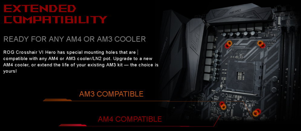
Board Galerie
BIOS
Latest (für Zen3): CROSSHAIR-VI-HERO-ASUS-8503.ZIP (2022/03/28, Update: AMD AM4 AGESA V2 PI 1.2.0.6b.)
Latest: CROSSHAIR-VI-HERO-ASUS-8101.ZIP (2021/08/16, Update: Suppot Windows 11)
ASUS: Please update to 0902 or later ASAP to avoid bricking your motherboard.
Inoffizielle BIOS Versionen u.a. für Extrem-OC (Achtung: Nutzung auf eigene Gefahr!)
- CROSSHAIR-VI-HERO-ASUS-0090 (Has some performance tweaks for Geekbench3, has BIOS updating bug on some boards.)
- CROSSHAIR-VI-HERO-ASUS-1001 (1T, Restore defaults before flashing, or use USB BIOS Flashback)
- CROSSHAIR-VI-HERO-ASUS-0038 (Same as 1001 but DRAM set to 2T mode, better on some systems)
- CROSSHAIR-VI-HERO-ASUS-1002 (1001 + bugfixes)
- CROSSHAIR-VI-HERO-ASUS-0079 (see spoiler)
Test BIOS with new AGESA 1004a, with a couple of bugfixes. Up to 5% performance increases in specific applications. Also has P-state overclocking working with BCLK increase. If you want to keep C-states, make sure to set Advanced\AMD CBS\Zen Common Options\Global C-state Control = Enabled. There are two new settings under AMD CBS\UMC Common Options\DDR4 Common Options\ you might want to take a look at, Fail_CNT and ProcODT. Fail_CNT decides how many times to retry when DRAM training fails (F9 -> 0d), default is now 1. ProcODT can help improve your DRAM overclocking. There's a setting available also on previous BIOSes under AMD CBS\UMC Common Options\DRAM Memory Mapping named BankGroupSwap. If you have 2x Single-Rank modules you can try setting this to Disabled and you might see some performance boost in certain applications. - CROSSHAIR-VI-HERO-ASUS-0081 (0079 + ProcODT default @ 53.3 ohm)
- CROSSHAIR-VI-HERO-ASUS-0082 (0081 + enhanced mememory compatibility)
CMK16GX4M4A2133C13
AHU08GGB13CGT7G
PV416G240C5QK
F4-2400C15Q-32GRR
TCD44G2400C14BK
F4-2666C16Q2-64GRB
AVD4UZ126661504G
BLT8G4D26AFTA.16FAD
IMA41GU6MFR8N-C F0
MD16GK4D4266615AXR
HX430C15PB2K4/16
HX430C15PBK4/32
AX4U3333W4G16-QGZ
GAM4DBLBM2133D15IE041C
TC48G24S817
SP004GBLFU213N02
78.C1GM3.AF10B
F4-3200C16D-8GVKB
MTA4ATF51264AZ-2G6B1
MTA8ATF1G64AZ-2G3B1
MTA16ATF2G64AZ-2G6B1
HMA41GU7AFR8N-TF T0
HMA451U7AFR8N-TF T0
HMA41GU6AFR8N-UH N0
M378A2K43BB1-CTD
M378A1K43BB1-CRC
M378A1G43EB1-CRC - CROSSHAIR-VI-HERO-ASUS-0083 (0081 + 2T command rate at 2666+)
- CROSSHAIR-VI-HERO-ASUS-9943 (Added Mem-Ratios: 3066, 3333, 3466, 3600, 3733, 3866, 4000 & manual Command Rate)
- CROSSHAIR-VI-HERO-ASUS-9945 (9943 + tweaks for 4x Hynix & 4x8GB Samsung 8Gb B-Die)
- CROSSHAIR-VI-HERO-ASUS-1401 (AGESA 1.0.0.6 RC4 based)
- CROSSHAIR-VI-HERO-ASUS-1403 (1401 + several Fixes: W_PUMP/AIO_PUMP, Fan Tuning, AMD USb 3.1, tRDRD_Sc, DRAM Boot Voltage)
- CROSSHAIR-VI-HERO-ASUS-9920 (Improved cold boot, fix stuck CPU ratio, SenseMi Skew default disabled, added memory OC profiles)
- CROSSHAIR-VI-HERO-ASUS-1501 (stuck CPU ratio workaround, fixes PCIEX4 bandwidth setting, DRAM boot behavior as 1403, memory OC profiles)
emissary42 schrieb:Falls ihre eine dieser Versionen testen wollt und der jeweilige Downloads nicht mehr verfügbar ist, schreibt mich deswegen im Thread an.
News & Reviews
- AMD Ryzen 7 1700 im Test und übertaktet - der interessanteste Ryzen - Hardwareluxx ft. ASUS ROG Crosshair VI Hero
[*]AMDs Ryzen 7 1700X im Test: Der beste Ryzen? - Hardwareluxx ft. ASUS ROG Crosshair VI Hero
[*]16 Threads für 550 Euro: AMD RYZEN 7 1800X im Test - Hardwareluxx ft. ASUS ROG Crosshair VI Hero - [Review] ASUS ROG Crosshair VI Hero @ KitGuru
- [Review] ASUS ROG Crosshair VI Hero @ Guru3d
- [Review] ASUS ROG Crosshair VI Hero @ LanOC
- [Review] ASUS ROG Crosshair VI Hero @ OC3D Review
- [Review] ASUS ROG Crosshair VI Hero @ bit-tech.net
- [Review] ASUS ROG Crosshair VI Hero + AMD Ryzen 7 1800X vs Intel Core i7-6900K @ benchlife.info
- [Review] ASUS ROG Crosshair VI Hero @ Tweaktown
- [Review] ASUS ROG Crosshair VI Hero @ HKEPC Hardware (cn)
- [Review] ASUS ROG Crosshair VI Hero @ Chiphell (cn)
- [Review] ASUS ROG Crosshair VI Hero @ ThinkComputers.org
- [Review] ASUS ROG Crosshair VI Hero @ Overclockers
- [Review] ASUS ROG Crosshair VI Hero @ Play3r
- [Review] ASUS RoG Crosshair VI Hero @ eTeknix
- [Review] ASUS ROG Crosshair VI Hero @ GreenTechReviews
- [Review] ASUS ROG Crosshair VI Hero @ HardOCP
- [Review] ASUS ROG Crosshair VI Hero @ Bjorn3D.com
- [Review] ASUS ROG Crosshair VI Hero @ Planet 3DNow!
- [Roundup] AM4 X370 Three-way shootout! @ AMDwallpapers
ASUS ROG Crosshair VI Hero
ASUS Prime X370 Pro
MSI X370 Gaming Pro Carbon - [Roundup] X370 Motherboard - Thermal Image Testing @ Legit Reviews
ASUS ROG Crosshair VI Hero (Bios 1001)
Gigabyte Aorus AX370-Gaming 5 (Bios F5d)
MSI X370 Xpower Gaming Titanium (Bios 1.26)
Hardwareluxx CPU-Kühler & RAM-Kompatibilitätsliste
1) CPU-Kühler
- Hersteller Modell @ Preisvergleich | Quelle | kompatibel | Einschränkungen / Anmerkungen
- Hersteller Modell @ Preisvergleich | Quelle | inkompatibel | Grund/Foto(s)
- Alphacool Eisbaer 280 (11287) | Powl | kompatibel | bei mir montiert mit AM4 Bracket, auf dem C6H dürfte auch das AM3 Kit passen
- Alphacool Eisblock XPX (12565) | crossbone | kompatibel
- Aqua Computer Cuplex Kryos HF (21561) | ResamBs | kompatibel | mit AM3-Halterungsbleche und Backplate montiert
- be quiet! Silent Loop 280mm (BW003) | Raspo | kompatibel | mit AMD Backplate
- Be Quiet! Dark Rock 3 (BK018) | Cippoli | kompatibel | Be Quiet! AM4-Kit notwendig
- Corsair Hydro H100i (CW-9060009-WW) | JCM900 | kompatibel |
- Corsair Hydro H110i GTX (CW-9060020-WW) | samsungstory | kompatibel | mit AM3+/AM4 Halterung
- Corsair Hydro H115i (CW-9060027-WW) | samsungstory | kompatibel | mit AM3+/AM4 Halterung
- EKL Alpenföhn Brocken 2 PCGH-Edt. | phoenix86 | kompatibel | passt mit dem EKL AM4-Montagekit [Anmerkungen]
- Noctua NH-D15 SE-AM4 | Achim Junker | kompatibel | Anmerkungen siehe [1]
- NZXT Kraken X62 (RL-KRX62-01) | Robär | kompatibel | Kontakt mit DIMM A1, lässt sich aber nutzen
- Scythe Mugen 5 (SCMG-5000) | cyberjfb | kompatibel | AM4 Halterung, Lüfter überdeckt Speicherbänke nicht
- Thermalright HR-02 Macho Rev. B | SaschaS | kompatibel | mit AM3+/AM4 Halterung
- --> Bitte helft mit sammeln!
Achtung, es gibt nun auch einen Monoblock von EK (ab 12.05.17): Press Release & EK-FB ASUS C6H RGB Monoblock - Nickel @ EK Shop


2) RAM
- Hersteller Modell @ Preisvergleich | Anzahl Module x Größe | Ranks | Quelle | kompatibel | Einschränkungen / Anmerkungen / Screenshots
- Hersteller Modell @ Preisvergleich | Anzahl Module x Größe | Ranks | Quelle | inkompatibel | Grund
- 2x Corsair Dominator Platinum CMD16GX4M2B3200C16 | 4x8GB | 2Rx8 | istanbul | kompatibel | Bios 0902-1002 @ DDR4-2666 14-15-15-30-1T [1]
- Corsair Dominator Platinum CMD32GX4M4B3200C16 | 4x8GB | 2Rx8 | kompatibel | The American | Bios 1401 @ DDR4-2933 CL16-18-18-36
- Corsair Vengeance LED CMU32GX4M4C3400C16 | 4x8GB | 1Rx8 | Powl | kompatibel | Bios 1002 @ 2x8GB DDR4-3200 CL14 (4x8GB @ Default)
- Corsair Vengeance LPX CMK16GX4M2B3000C15 | 2x8GB | 1Rx8 | cyberjfb | kompatibel | Bios 1002 @ DDR4-3050 16-16-16-35-1T (2933 * BCLK 104)
- Corsair Vengeance LPX CMK32GX4M2B3000C15W | 2x16GB | 2Rx8 | Robär | kompatibel | nur bis DDR4-2666 (BIOS 1002)
- Corsair Vengeance LPX CMK16GX4M2B3000C15 | 2x8GB | ? | Hardwareluxx Test | kompatibel |
- 2x Corsair Vengeance LPX CMK16GX4M2B3000C15 | 4x8GB | 1Rx8 | cyberjfb | kompatibel | Bios 1403 @ DDR4-3066 16-16-16-35-1T[1]
- Corsair Vengeance LPX CMK32GX4M2B3000C15 | 2x16GB | 2Rx8 | Cippoli | kompatibel | 1403 @ DDR4-2933 15-17-17-35-52 2T 1.35V [1] [2] [3]
- Corsair Vengeance LPX CMK16GX4M2B3000C15 | 2x8GB | 1Rx8
- Corsair Vengeance LPX CMK32GX4M2B3200C16 (Ver5.39) | 2x16GB | 2Rx8 | SaschaS | kompatibel | Bios 0082 @ DDR4-2720 16-16-16-39-1T (BCLK 102)
- Corsair Vengeance LPX CMK16GX4M2B3200C16 (Ver5.39) | 2x8GB | 1Rx8
- Corsair Vengeance LPX CMK16GX4M2B3200C16 | 2x8GB | 1Rx8 | Elzoco | kompatibel | Bios 1002 @ DDR4-3200 [1]
- Crucial Ballistix Elite BLE4C8G4D30AEEA | 4x8GB | 2Rx8 | e-spike | kompatibel | Bios 9920 @ DDR4-2950 16-16-16-36-1T
- Crucial Ballistix Sport LT BLS2K8G4D30AESCK | 2x8GB | 1Rx8 | sanni | kompatibel | Bios 7403 @ DDR4-3600 CL14-19-14-36 1.44V
- Galax HOF HOF4CXLBS4000M19SF162C | 2x8GB | 1Rx8 | Review | kompatibel | Bios 9920 @ DDR4-3466/3600 siehe Spoiler
2x8GB DDR4-3466 14-15-13 1T (1.40V)
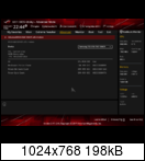
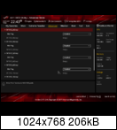
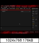
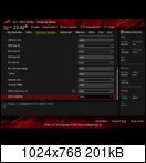
Anhang anzeigen 416237 Anhang anzeigen 416241 Anhang anzeigen 416242
2x8GB DDR4-3600 16-16-16 2T (1.44-1.48V)
Anhang anzeigen 416240 Anhang anzeigen 416238 Anhang anzeigen 416239
Quelle: [Review] KFA2 Hall Of Fame HOF4CXLBS3600K17LD162C & HOF4CXLBS4000M19SF162K @ Overclockers.ru - G.Skill Flare X F4-3200C14D-16GFX | 2x8GB | 1Rx8 |
- 2x G.Skill Flare X F4-3200C14D-16GFX | 4x8GB | 1Rx8 | R0N1N | kompatibel | @ XMP (DDR4-3200 14-14-14-34 1T)
- G.Skill RipJaws 4 F4-2800C16Q-32GRK | 4x8GB | 2Rx8 | JCM900 | kompatibel | Bios 1001 @ DDR4-2666 16-16-16-39-1T
- 2x G.Skill Ripjaws V F4-3200C16D-16GVKB | 4x8GB | 2Rx8 | yakuza82 | kompatibel | Bios 1501 @ DDR4-2933 14-16-16 [1]
- G.Skill Ripjaws V F4-3200C16D-32GVKA | 2x16GB | 2Rx8 | Gore6 | kompatibel | Bios 1501 @ DDR4-2933 14-16-16
- G.Skill Ripjaws V F4-3200C15D-32GVR | 2x16GB | 2Rx8 | MajorX99 | kompatibel | Bios 3502 @ DDR4-3200 via DOCP [1]
- G.Skill Trident Z F4-3000C14D-32GTZ | 2x16GB | 2Rx8 | chrischek | kompatibel | Bios 1002 @ DDR4-2666 14-14-14-34 1T
- G.Skill Trident Z F4-3200C14D-16GTZ | 2x8GB | 1Rx8 |
- G.Skill Trident Z F4-3200C14Q-32GTZ | 4x8GB | 1Rx8 | ileus | kompatibel | 1401 @ DDR4-3333 14-14-14 1.38V (1.45V Boot, +0.0125V SOC)
- G.Skill Trident Z F4-3200C14D-32GTZ | 2x16GB | 2Rx8 |
- G.Skill Trident Z F4-3200C15Q-32GTZSW | 4x8GB | 1Rx8 | Robär | kompatibel | lauffähig bis DDR4-3600
- G.Skill Trident Z F4-3400C16Q-64GTZ | 4x16GB | 2Rx8 | musicismylife | kompatibel | Bios 1001 @ DDR4-3000 14-14-14-39 1T 1.325V [1]
- G.Skill Trident Z RGB F4-3000C15D-16GTZR | 2x8GB | 1Rx8 | byowa | kompatibel | Bios 1401 @ DDR4-3200 manuell
- G.Skill Trident Z RGB F4-3000C14Q-32GTZR | 4x8GB | 1Rx8 | Chakka89 | kompatibel | Bios 9920 @ DDR4-3333 14-14-14-34 1T (Settings siehe Spoiler)

Mainboard:
- AMD Ryzen R7 1800X Eight-Core Processor
- ASUS ROG CROSSHAIR VI HERO
- BIOS Version: 9920 x64
- Build Date: 07/21/2017


AIDA64 Benchmark und Stabilitätstest erfolgreich, Memtest 6h erfolgreich, dazu Cinebench-Werte.

Meine Timings:
Meine Einstellungen - G.Skill Trident Z RGB Series, DDR4-3000, CL 14 - 32 GB Quad-Kit
Extreme Tweaker
- CPU SOC Voltage = 1,15000
- DRAM Voltage = 1.40000
Extreme Tweaker \ DRAM Timing Control
- ProcODT_SM = 53 ohm
- G.Skill Trident Z RGB F4-3200C16D-16GTZR | 2x8GB | 1Rx8 | Kurry | kompatibel | Bios 1401 @ DDR4-3200 via DOCP
- G.Skill Trident Z RGB F4-3200C14D-16GTZR | 2x8GB | 1Rx8 |
- G.Skill Trident Z RGB F4-3200C14Q-32GTZR | 4x8GB | 1Rx8 | Nachtviech | kompatibel | Bios 3008 @ 4x8GB DDR4-3466 14-14-14-30-1T 1.4 [RTC] [UEFI]
vorher:
G.Skill Trident Z RGB F4-3200C14Q-32GTZR | 4x8GB | 1Rx8 | Nachtviech | kompatibel | Bios 1701 @ 4x8GB DDR4-3333 14-14-14-28-1T 1.36V (Timings) - G.Skill Trident Z RGB F4-3600C17Q-64GTZR | 4x16GB | 2Rx8 | Ph03n!X | kompatibel | Bios 1401 @ 3200 14-14-14-39 1T 1.35V, ProcODT = 60 Ohm
- G.Skill Trident Z RGB F4-3600C16D-16GTZR | 2x8GB | 1Rx8 | armadillo | kompatibel | @ DDR4-3200 CL14
- Kingston HyperX Fury HX424C15FB2K4/32 | 4x8GB | 1Rx8 | samsungstory| kompatibel | Bios 0902 @ DDR4-2666 CL16
- --> Bitte helft mit sammeln!
ASUS Memory QVL (PDF).
Wer mir die Arbeit abnehmen möchte, kann seinen Eintrag gern direkt in diesem Format posten. Danke.
Nützliche Links & Tipps (im Forum & im WWW)
1) Hardwareluxx
- Ryzen RAM-OC a la Stunrise (aus dem ASUS Prime X370-Pro Sammelthread)
Anbei noch die versprochene Anleitung zum analytischen Übertakten des Arbeitsspeichers, wenn man bei Stabilität und Performance keine faulen Kompromisse eingehen will.
1: CPU-Core auf Standard
Es ist wichtig, unnötige Fehlerquellen auszuschließen. Deshalb sollte der Prozessor selbst hier mit Standard-Spannung und Standard-Takt laufen, keine unnötigen Spielereien!
2: Schaltet sämtliche Energiesparoptionen sowohl in Windows, als auch im BIOS aus.
- Deaktiviert den EPU Power Saving Mode (AI Tweaker)
- VDDCR SOC Load Line Calibration: Level 3 (Digi+VRM)
- VDDCR SOC Current Capability: 130% (Digi+VRM)
- VDDCR SOC Power Phase Control: Extreme (Digi+VRM)
- Energiesparprofil: Höchstleistung (Windows Systemsteuerung)
- Power Down Enable: Disabled (DRAM Timing Control)
-> Die LLC Stufe 3 liefert die Spannung am konstantesten und hat die geringstmögliche Differenzen zwischen Idle- und Loadspannung, sodass wir hier Fehlerursachen ausschließen. Die anderen Optionen dienen dazu, dass kein Throttling einsetzt (Capability) und dass alle Phasen auch dauerhaft verwendet werden, ansonsten wird zwecks Energiesparen immer nur so wenig wie möglich Phasen verwendet. Wofür ein Board mit vielen Phasen kaufen, wenn man alle abgeschaltet lässt?
3: Ausloten des maximal stabilen Speichertakts
- Beginnt zunächst mit folgenden Spannungen: 1,35v (vMemory) | 1,1v (vSoC) | ProcODT 53Ohm
- VTTDDR muss immer genau die Hälfte von vMemory sein, bei 1,35v vMem also 0,675v und bei 1,4v vMEM 0,7v VTTDDR
- Setzt alle Timings auf Auto, außer die Haupttimings auf 18-18-18-18-40-60. Lässt den Gear Down Mode aktiv und den ganzen Rest auf Auto. Finger weg von irgendwelchem Tuning der Timings, die bleiben lasch und das ist auch gut so!
- Ihr braucht für die Tests unbedingt HCI Memtest, ich empfehle die Pro Version für 5€, ich hab dafür auch einen Launcher geschrieben, der die Fenster alle automatisch öffnet und anordnet. Video + Anleitung. Lasst euch Zeit, wenn ein HCI Lauf mehr als 100% gut läuft, bricht ihn nicht ab und schreibt OK. Stabil ist erst, was eine Nacht HCI Memtest ohne Fehler übersteht!
- Solltet ihr so merkwürdige Probleme haben, dass HCI immer erst bei 1000% einen einzelnen Fehler wirft oder es die ganze Nacht gut war und du dann den Browser öffnest und zack hast du einen Fehler, dann müsst ihr mit der SoC Spannung rauf! Wenn ihr hier etwas mehr habt, ist das völlig egal, die Optimale Spannung wird erst am Schluss ausgelotet. Ihr müsst nur aufpassen, dass die Spannung selbst nicht Probleme verursacht, wenn ihr also 1,20v SoC einen Fehler bekommt und bei 1,15v nicht, dann nimmt natürlich das 1,15v.
- Manchmal ist das Board zickig bei Änderungen im BIOS und startet pauschal nicht, egal ob die eingestellten Werte stabil sind! Nicht sofort aufgeben, wenn ich nur eine Kleinigkeit ändere (z.B. vMemory von 1,375 auf 1,38v) und es plötzlich gar nicht mehr startet, dann probiert es einfach erneut. Diese Auffälligkeit ist hin und wieder nach einer Änderung einfach einmalig da.
- Beginnt mit 3200Mhz und versucht diese mit den folgenden drei Attributen zum laufen zu bekommen: vMemory, vSoC und ProcODT. Alle anderen Einstellungen auf Standard belassen. Ihr solltet euch in folgenden Rahmen bewegen: 1,35 - 1,45v (vMemory), 1,05 - 1,20v (vSoC) und 48Ohm, 53Ohm und 60Ohm bei ProcODT. Bei ProcODT ist die allgemeine Empfehlung für B-Die am ehesten 53Ohm, den würde ich erstmal so setzen und nur dann modifizieren, wenn ich den Takt nicht mit den Variablen vSoC und vMemory zum laufen bekomme. Versucht jetzt die 3200Mhz mit verschiedenen Kombinationen von vMEM 1,35v - 1,45v und vSoC 1,05v - 1,2v, am besten jeweils in 0,025v Schritten ausgelotet zu erreichen. Man entwickelt relativ schnell ein Gespür dafür, ob eine Einstellung jetzt schlechter oder besser ist. Wenn ich vorher mit 1,05v SoC nichtmal richtig booten kann und mit 1,15v das soweit schon wunderbar funktioniert, ich aber in HCI Fehler bekomme, ist das ja schon viel besser und der richtige Weg. Wenn ich mit 1,35v vMEM direkt nach 10% einen Fehler bekomme und 1,4v bis 100% ohne Fehler laufen, bin ich hier auf dem richtigen Weg. Auf diese Art und Weise muss man sich hier mühsam und quälend herantasten.
- Solltet ihr eine stabile 3200Mhz Einstellung finden, versucht euer Glück mit 3333Mhz und eventuell 3466Mhz, solange bis ihr genug habt oder nicht mehr weiterkommt, weil alle Kombinationen nicht stabil sind
- Wenn ihr fertig seid, testet sicherheitshalber nochmal mit Prime95 Blend mit 80% von eurem Speicher. Wenn ihr hier Probleme habt, müsst ihr vSoC erhöhen, weil HCI den Controller nicht stark belastet, dafür ist Prime95 ideal. Mit mehr vSoC solltet ihr hier schnell Erfolg haben.
-> Wichtig: Schreibt euch eure Ergebnisse auf, weil ihr nach 30 Versuchen nicht mehr wisst, was am Anfang rausgekommen ist und ihr somit einige Werte sonst doppelt prüfen würdet.
-> Dieser Punkt ist am wichtigsten und wenn man hier erfolgreich fündig wird, hat man mehr als 50% der Arbeit hinter sich. Die Timings sind nur noch Formsache, dieser Punkt hier ist das knackigste! Lasst euch Zeit und nicht zu schnell entmutigen, es ist durchaus normal, wenn man hier auch nach 3 Stunden noch kein brauchbares Ergebnis hat.
4: Maximale Haupt Timings ermitteln
Wenn ihr eine Einstellung gefunden habt, die HCI Memtest und Prime95 stabil durchläuft, dann sind dafür die Einstellungen vSoC und ProcODT validiert und versiegelt. Tastet euch jetzt an die maximalen Timings (Haupt) heran und geht hier in Gruppen vor: Die erste Gruppe sind die ersten vier Timings, die alle gleich und einen geraden Wert haben sollten, ungerade Werte starten oft nicht. Also versucht hier 14-14-14-14 oder 16-16-16-16. Wenn ihr hier Probleme habt, könnt ihr noch mit der vMemory Spannung rauf oder runter und prüfen, ob es damit besser wird. Wenn ihr hier irgendwann eure maximalen Haupttimings habt, würde ich sowohl Takt, als auch Haupttimings, vSoC, ProcODT und vMemory nicht mehr anfassen, diese sind vorher als stabil getestet worden und müssen so bleiben. Eure einzige Variable ist jetzt noch die einzelnen Subtimings
-> Wie auch bei dem Takt lasst euch nicht entmutigen, wenn das Board direkt in den Fail Safe Mode startet! Manchmal zickt das Board bei Änderungen einmal herum, obwohl die Werte stabil sind. Einfach dann nochmal setzen. Die Stabilität wird mit HCI getestet und nicht davon, ob der PC startet, weil das wie gesagt oft buggy ist, einfach nochmal probieren.
5: Maximale Subtimings ermitteln
Lotet jetzt jeden einzelnen Subtimingwert aus. Fangt mit tRAS an, stellt ihn auf den bestmöglichen Wert. Als bestmöglichen Wert würde ich immer die Stilt UHQ B-Die 3200Mhz Werte nehmen. Ändert immer nur einen Wert auf einmal. Durch das in Schritt 3 und 4 validierte Setting könnt ihr sicher sein, dass wenn ein Fehler auftaucht, dieser garantiert wegen dem geänderten Timing Wert kommt. Wenn ein Wert dann eine Nacht in HCI Memtest stabil war, könnt ihr diesen Timing Wert mit in die stabile Konfiguration mit aufnehmen. In ganz seltenen Fällen kann es vorkommen, dass ihr bei nachfolgenden Timings Probleme habt, egal wie ihr diese einstellt - dann liegt es daran, dass das vorherige Timing trotz einer Nacht HCI nicht 100% stabil war und die Fehler bei dem darauffolgenden Timing noch daher kommen, dann müsst ihr eventuell an den vorherigen Timing nochmal ran - kam bei mir aber nicht einmal vor. Wenn ein Timing mehr 3 mal in nachfolgenden Timings mitgetestet wurde, könnt ihr diesen Wert versiegeln, also in die 100% stabile Konfig mit aufnehmen. Nicht vergessen: Wenn ich jetzt DDR4-3200-14-14-14-14-30 als rock stable identifiziert habe, teste ich damit weiter, z.B. DDR4-3200-14-14-14-14-30-46 und gehe nicht wieder auf 18-18-18 oder so zurück. Wenn es nicht läuft wird der unsichere Wert erhöht, dann geht es weiter mit DDR4-3200-14-14-14-14-30-48, solange bis die gesamte Kette stabil ist. Danach geht es mit dem nächsten Wert weiter, also DDR4-3200-14-14-14-14-30-52-4-6 usw.
Die bestmöglichen Werte werden zu 75% nicht stabil sein, ihr werdet meistens sehr schnell Fehler in HCI Memtest bekommen. Geht dann stufenweise um 1 oder 2 rauf, solange bis es eine Nacht HCI Memtest stabil ist. Die Werte tRRDS und tRRDL würde ich gemeinsam verwenden und zwar immer so, dass tRRDL 1,5x von tRRDS ist (tRRDS 4 = tRRDL 6 | tRRDS 5 = tRRDL 7 oder 8 | tRRDS 6 = tRRDL 9). Ebenso würde ich tRDRDSCL und tWRWRSCL sowie tWRWRSD und tWRWRSD sowie tRDRDSD und tRDRDDD als Pärchen verwenden (gleiche Timings). Ebenso könnt ihr dann auch versuchen, ob die Konfiguration ohne GearDownMode stabil läuft.
Tipp: Die wichtigsten Subtimings unter Ryzen sind tRDRDSCL und tWRWRSCL, dort solltet ihr versuchen, diese auf 2 zu bekommen.
6: BankGroupSwap
Wenn ihr alle Timings und Taktraten validiert habt, könnt ihr noch den BankGroupSwap und BankGroupSwapAlt Modus deaktivieren und wieder eine Nacht testen. Wenn auch das passt, könnt ihr schrittweise die Spannung reduzieren, um hier das Mimimum auszuarbeiten, solang bis es instabil wird. Die Spannung auf das minimum zu drücken, würde ich erst am Schluss machen. Nicht vergessen: Wenn ihr vSoC reduziert, immer auch Prime95 Blend testen, nicht nur HCI Memtest!
7: CPU-OC und Memory-OC kombinieren
Jetzt könnt ihr noch euer CPU-OC gemeinsam mit dem Memory OC testen. Wenn es Probleme gibt, liegt es definitiv am CPU-OC, weil das Memory OC 100% sicher validiert wurde. Eventuell ist das gesamte OC Potential geringfügig durch MemoryOC reduziert, weil die Temperaturen durch höheren Speichertakt und höheren vSoC doch merklich ansteigen (bei mir etwa 10°C zu 0,9v 2133Mhz) und das sozusagen passiv das OC-Potential geringfügig reduziert. Die endgültig Finale Konfig dann nochmal 1 Nacht durch HCI und 1 Nacht durch P95 Blend laufen lassen und ihr habt es geschafft.
Bei meinen Werten mit 3,7Ghz nicht verwundern lassen: Ich hab hier einfach einen OC-Krüppel, der nicht mehr rockstable packt. Zwar sind sogar 3,9Ghz Cinebenchstable und auch Gamestable bei 1,425v - in Prime05 bekomme ich aber nach wenigen Minuten Fehler und ein instabiles System ist doch Bullshit, dann lieber auf 5,4% Takt verzichten, dafür 40% weniger Stromverbrauch/Hitze/Lautstärke und einen (rock) stabilen Betrieb. Das liegt aber nicht am RAM, auch mit Standard-RAM geht hier nicht mehr.
8: Spannungen minimieren (Optional)
Wenn ihr die gesamte Konfiguration stabil habt, könnt ihr versuchen, noch weniger Spannung zu geben. Wie immer nur einen Wert ändern und prüfen, ob es damit noch läuft. Meines Erachtens nach würde ich da nicht zu viel Zeit rein stecken, weil das was ihr euch an Leistungsaufnahme durch weniger vMemory oder vSoC spart, verbraucht ihr 100x in den Testläufen.
Wenn ihr alle 6 Schritte durchgehalten habt, seid ihr die top 0,1% im Internet, die wirklich einen schnellen und stabilen Speicher unter Ryzen haben. Die ganzen Papiertiger in Internetforen haben zu mehr als 99% alle teilweise höchst instable Konfigurationen, die irgendwann wegen Abstürzen oder Fehlern ohnehin auf Auto gesetzt wird, während in der Signatur natürlich noch die Fantasiewerte stehen. Noch ein Tipp: Wenn ihr euch diese mega Arbeit gemacht habt, fasst nichts mehr davon an! Bleibt bei eurer BIOS-Version und bei eurer Einstellung, ein BIOS-Update, was beispielsweise die Auto-Werte ändert, könnte euch alles ruinieren!
PS: Die Anleitung bezieht sich ausschließlich auf Samsung B-Die 2x8GB Single Rank Speicher! Für Micron, Hynix, DualRank, Vollbestückung, usw kenne ich mich nicht aus und die Werte können zum Teil enorm abweichen. Das analytische Vorgehen selbst ist natürlich immer gleich, nur muss man z.B. für DualRank ganz andere ProcODT Werte eintragen (60-96), eventuell mit den RTT und CAD Werten spielen uvm.
Nochmal eine Auflistung meiner Settings:
AI Tweaker
CPU-Core Ratio: 37
CPU-Voltage: 1,275v (manual)
SoC-Voltage: 1,15v (manual)
Memory Frequency: 3333Mhz
DRAM Voltage: 1,375v
VTTDDR Voltage: 0,68750v
AI Tweaker / Digi+VRM
CPU Load Line Calibration: Level 3
CPU Current Capability: 130%
VRM Spread Spectrum: Off
CPU Power Duty Control: Extreme
CPU Power Phase Control: Extreme
SoC Load Line Calibration: Level 3
SoC Current Capability: 130%
SoC Power Phase Control: Extreme
AI Tweaker / DRAM Timing Control
ProcODT: 53 Ohm (48 hat auch funktioniert)
Cmd2T: 1T
Gear Down Mode: Disabled
Power Down Enable: Disabled
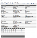
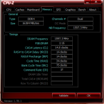
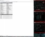
Alle Timings siehe Screenshot unten
Advanced / AMD CBS / DRAM Memory Mapping (nur im MOD BIOS verfügbar, THX an number9 und Reous)
BankGroupSwap: Disabled (egal für Stabilität, steigert aber Gaming Performance auf kosten von RAM Benchmark Leistung)
BankGroupSwapAlt: Disabled (egal für Stabilität, steigert Gaming Performance auf kosten von RAM Benchmark Leistung)
Alle nicht aufgeführten Einstellungen sind auf Auto!
Timings sind wie folgt

- [Übersicht] AMD AM4 Mainboards - News, Specs, Reviews Bilder (alle Plattformen)
- [Übersicht] AM4 Mainboard VRM Liste
[Sammelthread] AMD Ryzen Sockel AM4 (OC-Listen, Links, FAQ) Overclocking-Laberthread =-(alt)
--> [Sammelthread] AMD Ryzen (Zen) Socket AM4 OC Thread (aktuell)- [Übersicht] AMD GHz Club | Socket 940 - G34 | Socket 754 - AM4 | Socket FM1 - FM2+ | Socket AM1
- HowTo: 3200MT/s mit 2x16GB B-die Dual Rank auf ASUS Crosshair VI Hero (AM4, Ryzen) by curious
- Der offizielle ASUS Support direkt hier im Forum: ASUS
- Direktlink zum ASUS eSupport: per E-Mail & per Telefon
2) WWW (international)
- ASUS ROG Crosshair VI Hero Extreme Overclocking Guide (Updated to v0.5) - Overclocking.Guide
- ASUS ROG Crosshair VI Hero - XOC Guide @ C6H XOC Guide v05
- ASUS ROG Crosshair VI Hero - OC Software Pack @ C6HOCAK0302
OCPanel II firmware (wait for OC Panel I)
ROG Connect Plus
TurboV Core 1.01.15
MemTweakIt
X370 Windows 7 USB drivers
am4_pcratio_v03 - am4_pcratio_ccx sets ratio per core complex, am4_pcratio_focus sets a single core to requested ratio
zen_perfboost_v03 - Realtime tweaks for specific benchmarks including Cinebench R11.5, Cinebench R15 and Geekbench3 - ASUS Zen States (P-States in Windows anpassen): Download V0.2.2
- AMD Ryzen Overclocking Guide @ Overclockers
- Calculator timings v 0.9.1 + P-state Calculator + Ryzen records - Google Tabellen
- ASUS Aura firmware reflash/recovery tool @ ROG Forums
- The Stilt - Ryzen Timing Checker (RTC): [ Download : V1.00 ] | [ Download : V1.01 ]
- Ryzen Timings Calculator Downloads: v0.9.8 | v0.9.9
- ASUS ROG Crosshair VI Hero @ HWBOT
3) Tips & Tricks
FAQ - Frequently Asked Questions
- Q: Gibt es eine Empfehlung, welche ProcODT ich für meinen RAM einstellen soll?
- A:
Elmor[ASUS] schrieb:Samsung B (SR) 2x8 = 53.3 ohms
Samsung B (DR) 2x16 = 80 ohms
Samsung B (DR) 4x16 = 43.6 ohms
Hynix A (DR) 2x8 = 53.3 ohms
Hynix A (DR) 4x8 = 40 ohms
- Q: Gibt es empfehlen für Timings für DDR4-3200+ die ich testen kann?
- A: Für Samsung 8Gbit B-Die hat The Stilt folgendes getestet:
Für die Single Rank Hynix 8Gbit AFR & MFR Varianten:The Stilt schrieb:HQ B-die - 3200MHz "Safe" 1.350V
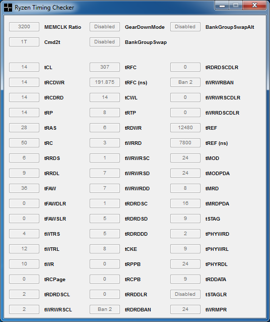
UHQ B-die - 3200MHz "Fast" 1.350V

HQ B-die - 3333MHz "Safe" 1.350V
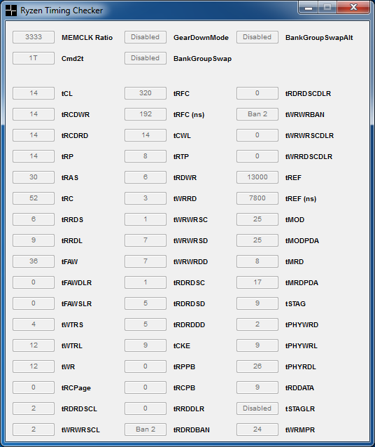
UHQ B-die - 3333MHz "Fast" 1.350V
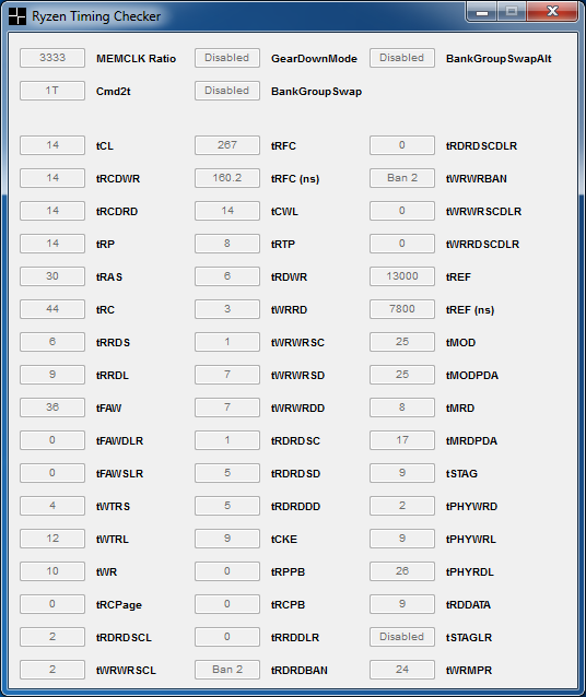
HQ = e.g. 3000C14, 3200C15, 3600C16, 3600C17 rated B-die kits
UHQ = e.g. 3200C14, 3600C15 rated B-die kits
These timings are stable on my 3600C15 kit with < 1.350V voltage (1.340V bios setting).
In 3200MHz "Fast" example, tCL 13 would be otherwise doable (this kit is rated 13.333 CLK tCL-tRCD-tRP timings at 3200MHz) however AGESA issue affecting tCWL prevents using it at the moment.
For the best real world performance disable both BankGroupSwap and BankGroupSwapAlternative options, when using 1 DPC SR modules.
The Stilt schrieb:Hynix AFR, 1DPC SR
"Safe"
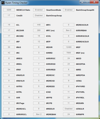
- ProcODT 60 Ohms
- DRAM Voltage / DRAM Boot Voltage 1.340V (keep these syncronized at all times)
- VDDCR_SOC 1.025V
"Extreme"
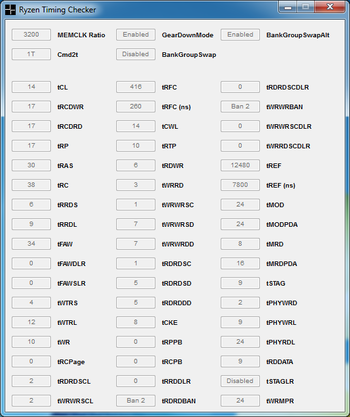
- ProcODT 60 Ohms
- DRAM Voltage / DRAM Boot Voltage 1.405V (keep these syncronized at all times)
- VDDCR_SOC 1.025V
Hynix MFR, 1DPC SR
"Safe"
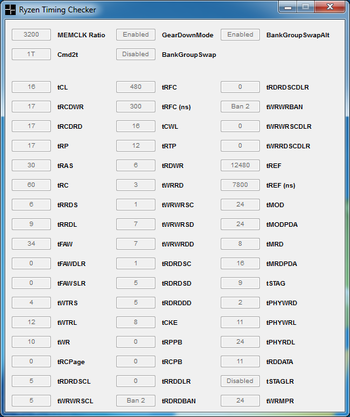
- ProcODT 60 Ohms
- DRAM Voltage / DRAM Boot Voltage 1.365V (keep these syncronized at all times)
- VDDCR_SOC 1.025V
"Fast"
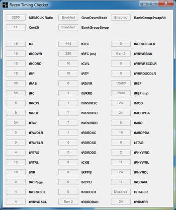
- ProcODT 60 Ohms
- DRAM Voltage / DRAM Boot Voltage 1.390V (keep these syncronized at all times)
- VDDCR_SOC 1.025V
- Q: Woher bekomme ich den Ryzen Balanced Power Plan?
- A: Er ist in den aktuellen Chipsatz-Treibern enthalten [Download].
- Q: Welche Loadline sollte ich beim übertakten verwenden?
- A:
The Stilt schrieb:Just keep the voltages at sane levels (< 1.45V for VDDCR_CPU, < 1.10V for VDDCR_SoC) and don't tamper with the load-line settings, unless you actually MEASURE significant amounts of droop, under load (which is not likely on C6H). Voltage overshoot hurts just as bad as undershoot, when it comes to stability. If you need to increase the load-line setting (i.e. introduce overshoot) to maintain stability, then your voltages are not set correctly to begin with.
The load-line options in bios translate to:
Auto = ±0% (1.425mOhm)
Level 1 = -40% (0.855mOhm)
Level 2 = -50% (0.7125mOhm)
Level 3 = -75% (0.35625mOhm)
Level 4 = -85% (0.21375mOhm)
Level 5 = -100% (0.0000mOhm)
I personally recommend to keep the load-line settings at "Auto" at all times, unless you are doing LN2 runs.
The main difference between the different Ryzen 7-series SKUs (aside of the clocks) is the leakage. The 1700 SKUs have low leakage characteristics, while both 1700X & 1800X are high(er) leaking silicon. Because of that 1700 requires even less load-line biasing than the other two (due the currents being lower).
- Q: Was bedeuten im neuen BIOS die ganzen zusätzlichen Einstellungen für den RAM?
- A: Im vierten Community Updae, wurden einige AGESA 1.0.0.6 spezifische Einstellungen erklärt [1].
Parameter Function Values Memory clocks Added dividers for memory clocks up to DDR4-4000 without refclk adjustment. Please note that values greater than DDR4-2667 is overclocking. Your mileage may vary (as noted by our big overclocking wartning at the end of this blog). 133.33MT/s intervals (2667, 2933, 3067, 3200, 3333, 3466, 3600, 3733, 3866, 4000) Command rate (CR) The amount of time, in cycles, between when a DRAM chip is selected and a command is executed. 2T CR can be very beneficial for stability with high memory clocks, or for 4-DIMM configurations. 2T, 1T ProcODT (CPU on-die termination) A resistance value, in ohms, that determines how a completed memory signal is terminated. Higher values can help stabilize higher data rates. Values in the range of 60-96 can prove helpful. Integer values (ohms) tWCL/tWL/tCWL CAS Write Latency, or the amount of time it takes to write to the open memory bank. WCL is generally configured equal to CAS or CAS-1. This can be a significant timing for stability, and lower values often prove better. Integer values (cycles) tRC Row cycle time, or the number of clock cycles required for a memory row to complete a full operational cycle. Lower values can notably improve performance, but should not be set lower than tRP+tRAS for stability reasons. Integer values (cycles) tFAW Four activation window, or the time that must elapse before new memory banks can be activated after four ACTIVATE commands have been issued. Configured to a minumum 4x tRRD_S, but values >8x tRRD_S are often used for stability. Integer values (ns) tWR Write recovery time, or the time that must elapse between a valid write operation and the precharging of another bank. Higher values are often beneficial for stability, and values < 8 can quickly corrupt data stored in RAM. Integer values (ns) CLDO_VDDP Voltage for the DDR4 PHY on the SoC. Somewhat counterintuitively, lowering VDDP can often be more beneficial for stability than raising CLDO_VDDP. Advanced overclockers should also know that altering CLDO_VDDP can move or resolve memory holes. Small changes to VDDP can have a big effect, and VDDP should not be set to a value greater than VDIMM-0.1V. A cold reboot is required if you alter this voltage.
Sidenote: pre-1.0.0.6 BIOSes may also have an entry labeled “VDDP” that alters the external voltage level sent to the CPU VDDP pins. This is not the same parameter as CLDO_VDDP in AGESA 1.0.0.6.Integer values (V) tRDWR / tWRRD Read-to-write and write-to-read latency, or the time that must elapse between issuing sequential read/write or write/read commands. Integer values (cycles) tRDRD / tWRWR Read-to-read and write-to-write latency, or the time between sequential read or write requests (e.g. DIMM-to-DIMM, or across ranks). Lower values can significantly improve DRAM throughput, but high memory clocks often demand relaxed timings. Integer values (cycles) Geardown Mode Allows the DRAM device to run off its internally-generated ½ rate clock for latching on the command or address buses. ON is the default for speeds greater than DDR4-2667, however the benefit of ON vs. OFF will vary from memory kit to memory kit. Enabling Geardown Mode will override your current command rate. On/Off Rtt Controls the performance of DRAM internal termination resistors during nominal, write, and park states. Nom(inal), WR(ite), and Park integers (ohms) tMAW Maximum activation window, or the maximum number of times a DRAM row can be activated before adjacent memory rows must be refreshed to preserve data. Integer values (cycles) tMAC Maximum activate count, or the number of times a row is activated by the system before adjacent row refresh. Must be equal to or less than tMAW. Integer values (cycles) tRFC Refresh cycle time, or the time it takes for the memory to read and re-write information to the same DRAM cell for the purposes of preserving information. This is typically a timing automatically derived from other values. Integer values (cycles) tRFC2 Refresh cycle time for double frequency (2x) mode. This is typically a timing automatically derived from other values. Integer values (cycles) tRFC4 Refresh cycle time for quad frequency (4x) mode. This is typically a timing automatically derived from other values. Integer values (cycles) tRRD_S Activate to activate delay (short), or the number of clock cycles between activate commands in a different bank group. Integer values (cycles) tRRD_L Activate to activate delay (long), or the number of clock cycles between activate commands in the same bank group. Integer values (cycles) tWR Write recovery time, or the time that must elapse between a valid write operation and the precharging of another bank. Higher values are often better for stability. Integer values (ns) tWTR_S Write to read delay (short), or the time between a write transaction and read command on a different bank group. Integer values (cycles) tWTR_L Write to read delay (long), or the time between a write transaction and read command on the same bank group. Integer values (cycles) tRTP Read to precharge time, or the number of clock cycles between a READ command to a row and a precharge command to the same rank. Integer values (cycles) DRAM Power Down Can modestly save system power, at the expense of higher DRAM latency, by putting DRAM into a quiescent state after a period of inactivity. On/Off
- Q: Was bedeutet der Debug Code XY?
- A: Hier eine relativ vollständige Liste, die Dracal ausgegraben hat (Achtung nicht alle Codes werden auch von jedem Board benutzt):
Ich bin gerade über die Vollständigste Q-Post Liste gestolpert die ich bisher gesehen habe vielleicht wäre das was für Seite 1 als Spoiler..
Progress Codes
00 - Not used
01 - Power on. Reset type detection (soft/hard)
02 - AP initialization before microcode loading
03 - System Agent initialization before microcode loading
04 - PCH initialization before microcode loading
05 - OEM initialization before microcode loading
06 - Microcode loading
07 - AP initialization after microcode loading
08 - System Agent initialization after microcode loading
09 - PCH initialization after microcode loading
0A - OEM initialization after microcode loading
0B - Cache initialization
SEC Error Codes
0C - Reserved for future AMI SEC error codes
0D - Reserved for future AMI SEC error codes
0E - Microcode not found
0F - Microcode not loaded
PEI Phase
10 - PEI Core is started
11 - Pre-memory CPU initialization is started
12 - Pre-memory CPU initialization (CPU module specific)
13 - Pre-memory CPU initialization (CPU module specific)
14 - Pre-memory CPU initialization (CPU module specific)
15 - Pre-memory System Agent initialization is started
16 - Pre-Memory System Agent initialization (System Agent module specific)
17 - Pre-Memory System Agent initialization (System Agent module specific)
18 - Pre-Memory System Agent initialization (System Agent module specific)
19 - Pre-memory PCH initialization is started
1A - Pre-memory PCH initialization (PCH module specific)
1B - Pre-memory PCH initialization (PCH module specific)
1C - Pre-memory PCH initialization (PCH module specific)
1D - OEM pre-memory initialization codes
1E - OEM pre-memory initialization codes
1F - OEM pre-memory initialization codes
20 - OEM pre-memory initialization codes
21 - OEM pre-memory initialization codes
22 - OEM pre-memory initialization codes
23 - OEM pre-memory initialization codes
24 - OEM pre-memory initialization codes
25 - OEM pre-memory initialization codes
26 - OEM pre-memory initialization codes
27 - OEM pre-memory initialization codes
28 - OEM pre-memory initialization codes
29 - OEM pre-memory initialization codes
2A - OEM pre-memory initialization codes
2B - Memory initialization. Serial Presence Detect (SPD) data reading
2C - Memory initialization. Memory presence detection
2D - Memory initialization. Programming memory timing information
2E - Memory initialization. Confi guring memory
2F - Memory initialization (other)
30 - Reserved for ASL (see ASL Status Codes section below)
31 - Memory Installed
32 - CPU post-memory initialization is started
33 - CPU post-memory initialization. Cache initialization
34 - CPU post-memory initialization. Application Processor(s) (AP) initialization
35 - CPU post-memory initialization. Boot Strap Processor (BSP) selection
36 - CPU post-memory initialization. System Management Mode (SMM) initialization
37 - Post-Memory System Agent initialization is started
38 - Post-Memory System Agent initialization (System Agent module specific)
39 - Post-Memory System Agent initialization (System Agent module specific)
3A - Post-Memory System Agent initialization (System Agent module specific)
3B - Post-Memory PCH initialization is started
3C - Post-Memory PCH initialization (PCH module specific)
3D - Post-Memory PCH initialization (PCH module specific)
3E - Post-Memory PCH initialization (PCH module specific)
3F - OEM post memory initialization codes
40 - OEM post memory initialization codes
41 - OEM post memory initialization codes
42 - OEM post memory initialization codes
43 - OEM post memory initialization codes
44 - OEM post memory initialization codes
45 - OEM post memory initialization codes
46 - OEM post memory initialization codes
47 - OEM post memory initialization codes
48 - OEM post memory initialization codes
49 - OEM post memory initialization codes
4A - OEM post memory initialization codes
4B - OEM post memory initialization codes
4C - OEM post memory initialization codes
4D - OEM post memory initialization codes
4E - OEM post memory initialization codes
4F - DXE IPL is started
PEI Error Codes
50 - Memory initialization error. Invalid memory type or incompatible memory speed
51 - Memory initialization error. SPD reading has failed
52 - Memory initialization error. Invalid memory size or memory modules do not match
53 - Memory initialization error. No usable memory detected
54 - Unspecifi ed memory initialization error
55 - Memory not installed
56 - Invalid CPU type or Speed
57 - CPU mismatch
58 - CPU self test failed or possible CPU cache error
59 - CPU micro-code is not found or micro-code update is failed
5A - Internal CPU error
5B - reset PPI is not available
5C - Reserved for future AMI error codes
5D - Reserved for future AMI error codes
5E - Reserved for future AMI error codes
5F - Reserved for future AMI error codes
DXE Phase
60 - DXE Core is started
61 - NVRAM initialization
62 - Installation of the PCH Runtime Services
63 - CPU DXE initialization is started
64 - CPU DXE initialization (CPU module specific)
65 - CPU DXE initialization (CPU module specific)
66 - CPU DXE initialization (CPU module specific)
67 - CPU DXE initialization (CPU module specific)
68 - PCI host bridge initialization
69 - System Agent DXE initialization is started
6A - System Agent DXE SMM initialization is started
6B - System Agent DXE initialization (System Agent module specific)
6C - System Agent DXE initialization (System Agent module specific)
6D - System Agent DXE initialization (System Agent module specific)
6E - System Agent DXE initialization (System Agent module specific)
6F - System Agent DXE initialization (System Agent module specific)
70 - PCH DXE initialization is started
71 - PCH DXE SMM initialization is started
72 - PCH devices initialization
73 - PCH DXE Initialization (PCH module specific)
74 - PCH DXE Initialization (PCH module specific)
75 - PCH DXE Initialization (PCH module specific)
76 - PCH DXE Initialization (PCH module specific)
77 - PCH DXE Initialization (PCH module specific)
78 - ACPI module initialization
79 - CSM initialization
7A - Reserved for future AMI DXE codes
7B - Reserved for future AMI DXE codes
7C - Reserved for future AMI DXE codes
7D - Reserved for future AMI DXE codes
7E - Reserved for future AMI DXE codes
7F - Reserved for future AMI DXE codes
80 - OEM DXE initialization codes
81 - OEM DXE initialization codes
82 - OEM DXE initialization codes
83 - OEM DXE initialization codes
84 - OEM DXE initialization codes
85 - OEM DXE initialization codes
86 - OEM DXE initialization codes
87 - OEM DXE initialization codes
88 - OEM DXE initialization codes
89 - OEM DXE initialization codes
8A - OEM DXE initialization codes
8B - OEM DXE initialization codes
8C - OEM DXE initialization codes
8D - OEM DXE initialization codes
8E - OEM DXE initialization codes
8F - OEM DXE initialization codes
90 - Boot Device Selection (BDS) phase is started
91 - Driver connecting is started
92 - PCI Bus initialization is started
93 - PCI Bus Hot Plug Controller Initialization
94 - PCI Bus Enumeration 32
95 - PCI Bus Request Resources
96 - PCI Bus Assign Resources
97 - Console Output devices connect
98 - Console input devices connect
99 - Super IO Initialization
9A - USB initialization is started
9B - USB Reset
9C - USB Detect
9D - USB Enable
9E - Reserved for future AMI codes
9F - Reserved for future AMI codes
A0 - IDE initialization is started
A1 - IDE Reset
A2 - IDE Detect
A3 - IDE Enable
A4 - SCSI initialization is started
A5 - SCSI Reset
A6 - SCSI Detect
A7 - SCSI Enable
A8 - Setup Verifying Password
A9 - Start of Setup
AA - Reserved for ASL (see ASL Status Codes section below)
AB - Setup Input Wait
AC - Reserved for ASL (see ASL Status Codes section below)
AD - Ready To Boot event
AE - Legacy Boot event
AF - Exit Boot Services event
B0 - Runtime Set Virtual Address MAP Begin
B1 - Runtime Set Virtual Address MAP End
B2 - Legacy Option ROM Initialization
B3 - System Reset
B4 - USB hot plug
B5 - PCI bus hot plug
B6 - Clean-up of NVRAM
B7 - Confi guration Reset (reset of NVRAM settings)
B8 - Reserved for future AMI codes
B9 - Reserved for future AMI codes
BA - Reserved for future AMI codes
BB - Reserved for future AMI codes
BC - Reserved for future AMI codes
BD - Reserved for future AMI codes
BE - Reserved for future AMI codes
BF - Reserved for future AMI codes
C0 - OEM BDS initialization codes
C1 - OEM BDS initialization codes
C2 - OEM BDS initialization codes
C3 - OEM BDS initialization codes
C4 - OEM BDS initialization codes
C5 - OEM BDS initialization codes
C6 - OEM BDS initialization codes
C7 - OEM BDS initialization codes
C8 - OEM BDS initialization codes
C9 - OEM BDS initialization codes
CA - OEM BDS initialization codes
CB - OEM BDS initialization codes
CC - OEM BDS initialization codes
CD - OEM BDS initialization codes
CE - OEM BDS initialization codes
CF - OEM BDS initialization codes
DXE Error Codes
D0 - CPU initialization error
D1 - System Agent initialization error
D2 - PCH initialization error
D3 - Some of the Architectural Protocols are not available
D4 - PCI resource allocation error. Out of Resources
D5 - No Space for Legacy Option ROM
D6 - No Console Output Devices are found
D7 - No Console Input Devices are found
D8 - Invalid password
D9 - Error loading Boot Option (LoadImage returned error)
DA - Boot Option is failed (StartImage returned error)
DB - Flash update is failed
DC - Reset protocol is not available
S3 Resume Progress Codes
E0 - S3 Resume is stared (S3 Resume PPI is called by the DXE IPL)
E1 - S3 Boot Script execution
E2 - Video repost
E3 - OS S3 wake vector call
E4 - Reserved for future AMI progress codes
E5 - Reserved for future AMI progress codes
E6 - Reserved for future AMI progress codes
E7 - Reserved for future AMI progress codes
S3 Resume Error Codes
E8 - S3 Resume Failed
E9 - S3 Resume PPI not Found
EA - S3 Resume Boot Script Error
EB - S3 OS Wake Error
EC - Reserved for future AMI error codes 31
ED - Reserved for future AMI error codes 31
EE - Reserved for future AMI error codes 31
EF - Reserved for future AMI error codes 31
Recovery Progress Codes
F0 - Recovery condition triggered by firmware (Auto recovery)
F1 - Recovery condition triggered by user (Forced recovery)
F2 - Recovery process started
F3 - Recovery fi rmware image is found
F4 - Recovery fi rmware image is loaded
F5 - Reserved for future AMI progress codes
F6 - Reserved for future AMI progress codes
F7 - Reserved for future AMI progress codes
Recovery Error Codes
F8 - Recovery PPI is not available
F9 - Recovery capsule is not found
FA - Invalid recovery capsule
FB - Reserved for future AMI error codes
FC - Reserved for future AMI error codes
FD - Reserved for future AMI error codes
FE - Reserved for future AMI error codes
FF - Reserved for future AMI error codes
ACPI/ASL Checkpoints
01 - System is entering S1 sleep state
02 - System is entering S2 sleep state
03 - System is entering S3 sleep state
04 - System is entering S4 sleep state
05 - System is entering S5 sleep state
10 - System is waking up from the S1 sleep state
20 - System is waking up from the S2 sleep state
30 - System is waking up from the S3 sleep state
40 - System is waking up from the S4 sleep state
AC - System has transitioned into ACPI mode. Interrupt controller is in APIC mode
AA - System has transitioned into ACPI mode. Interrupt controller is in APIC mode
- --> Deine Frage hier!
Das Schwestermodell mit integriertem 2x2 802.11ac Wi-Fi --> ROG CROSSHAIR VI HERO (WI-FI AC) | Motherboards | ASUS Global
Laut Treiber Download handelt es sich um eine Karte mit Qualcomm Atheros Chipsatz.
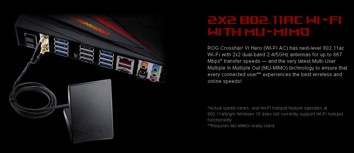
Edit: das Wi-Fi Modell besitzt außerdem eine eigene BIOS Nummerierung
Zuletzt bearbeitet:

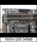

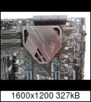
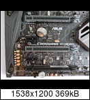

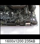


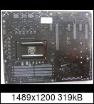

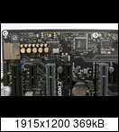
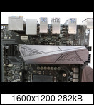
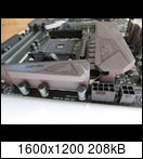


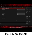

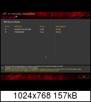


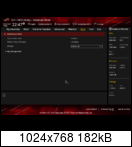


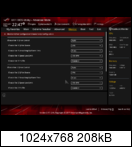














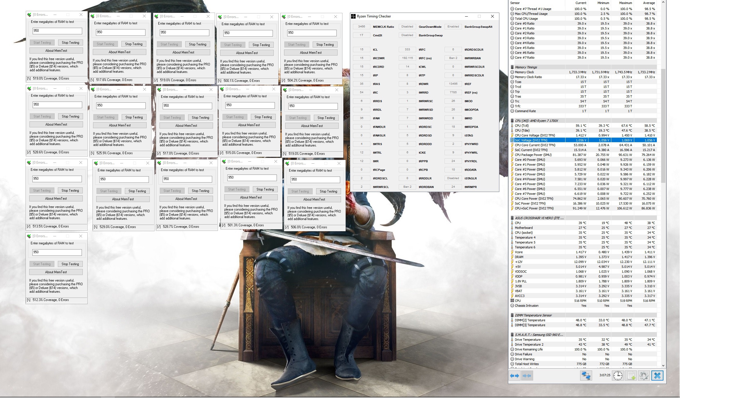


 wie haste das geschafft?
 damit folgt dann ggf. ein Doppelpost >