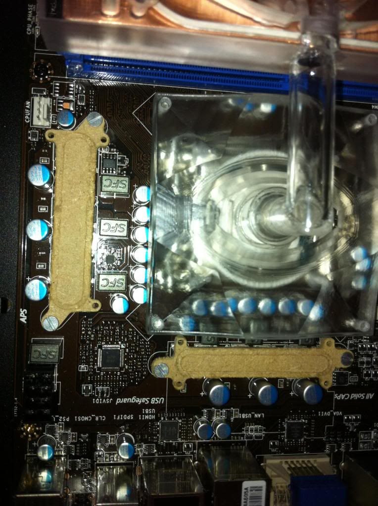
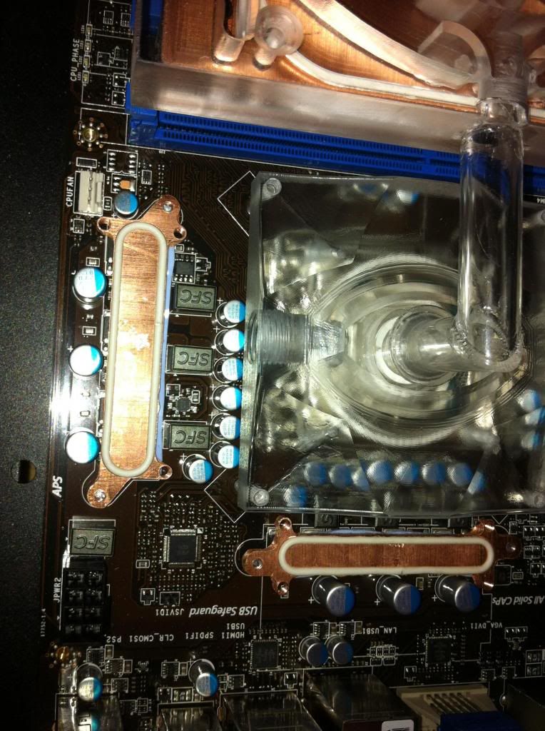
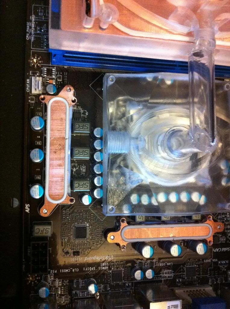
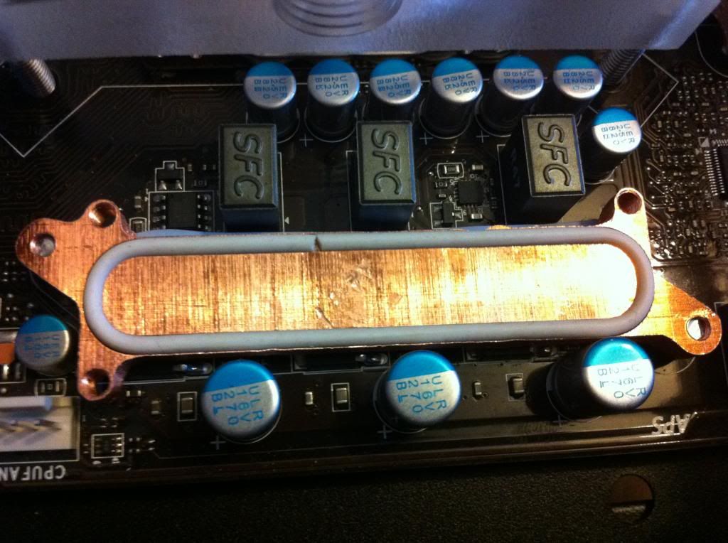
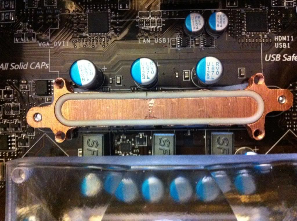
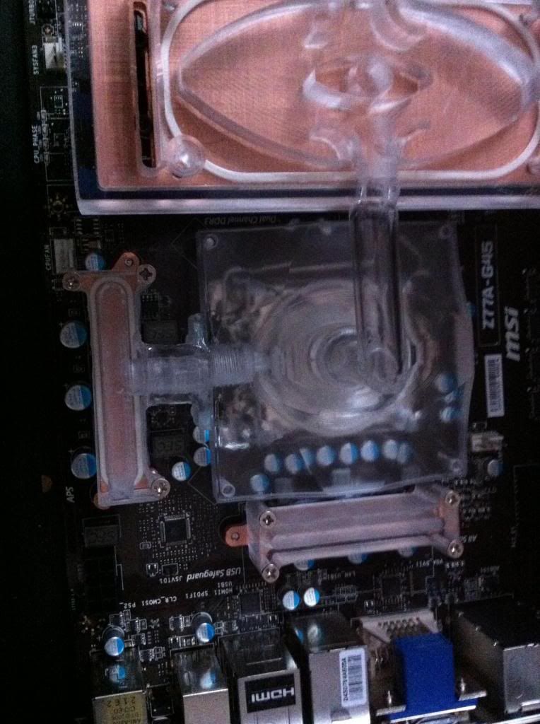
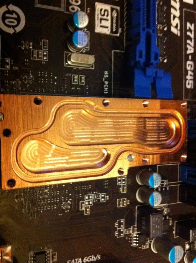
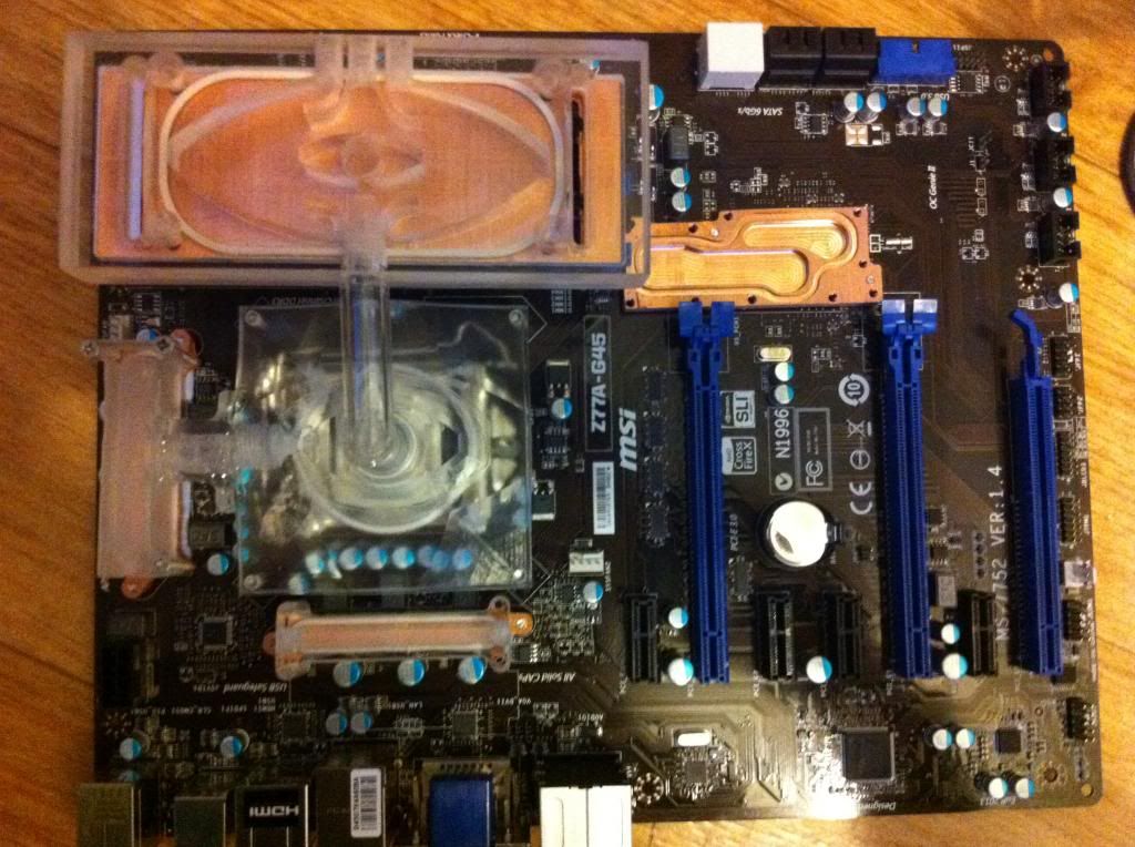
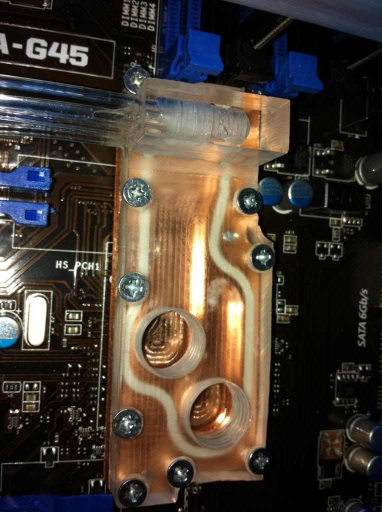
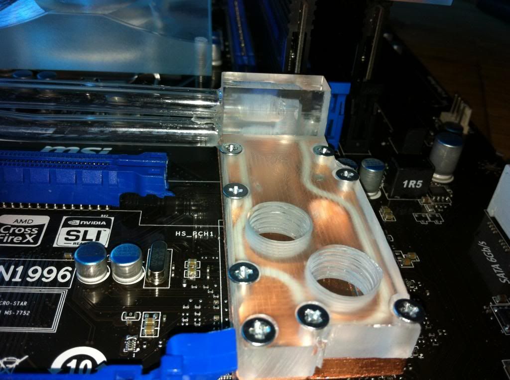
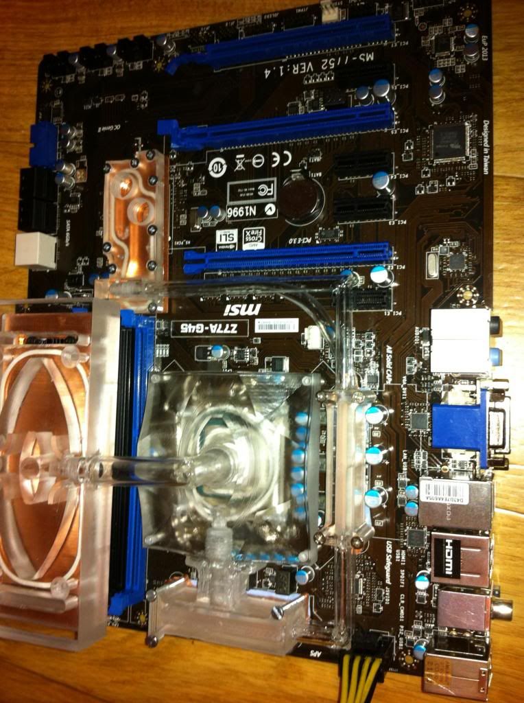
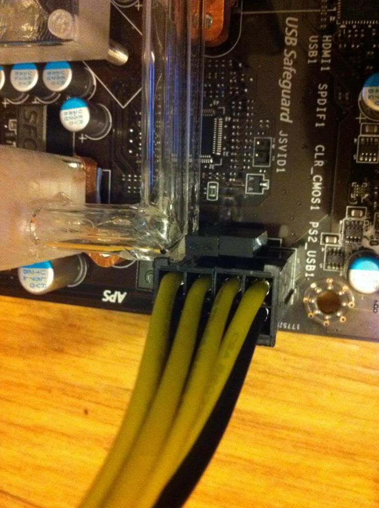
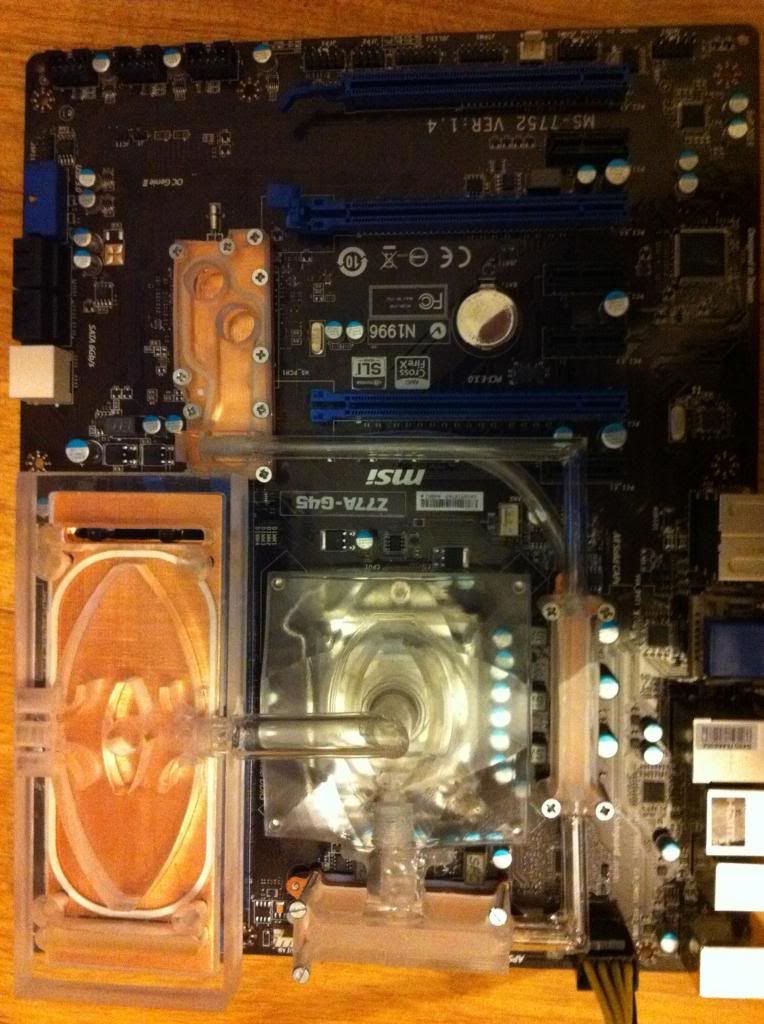
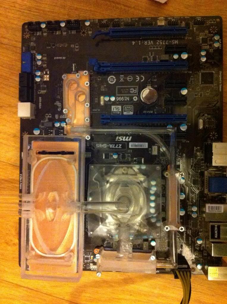
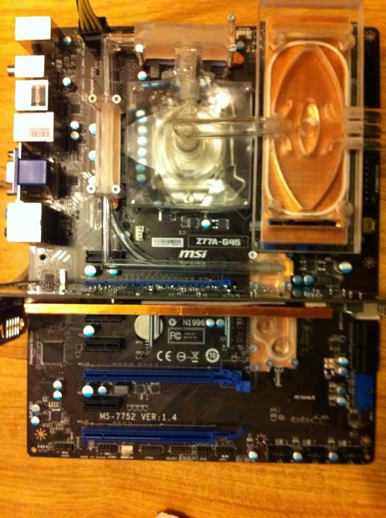
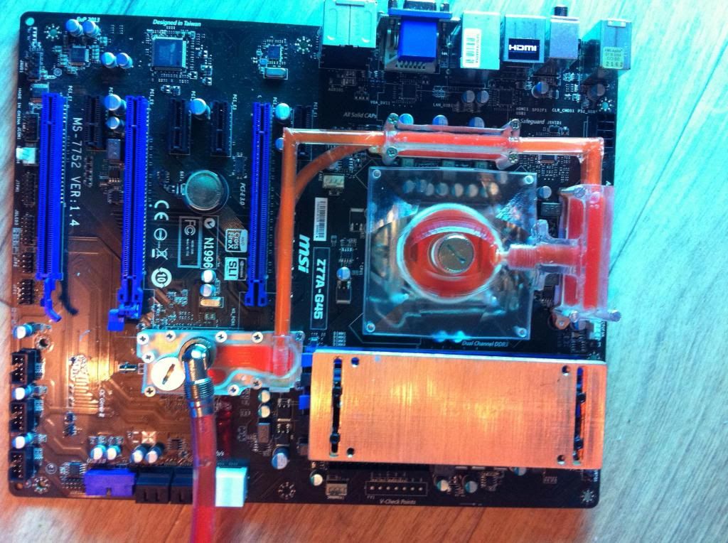
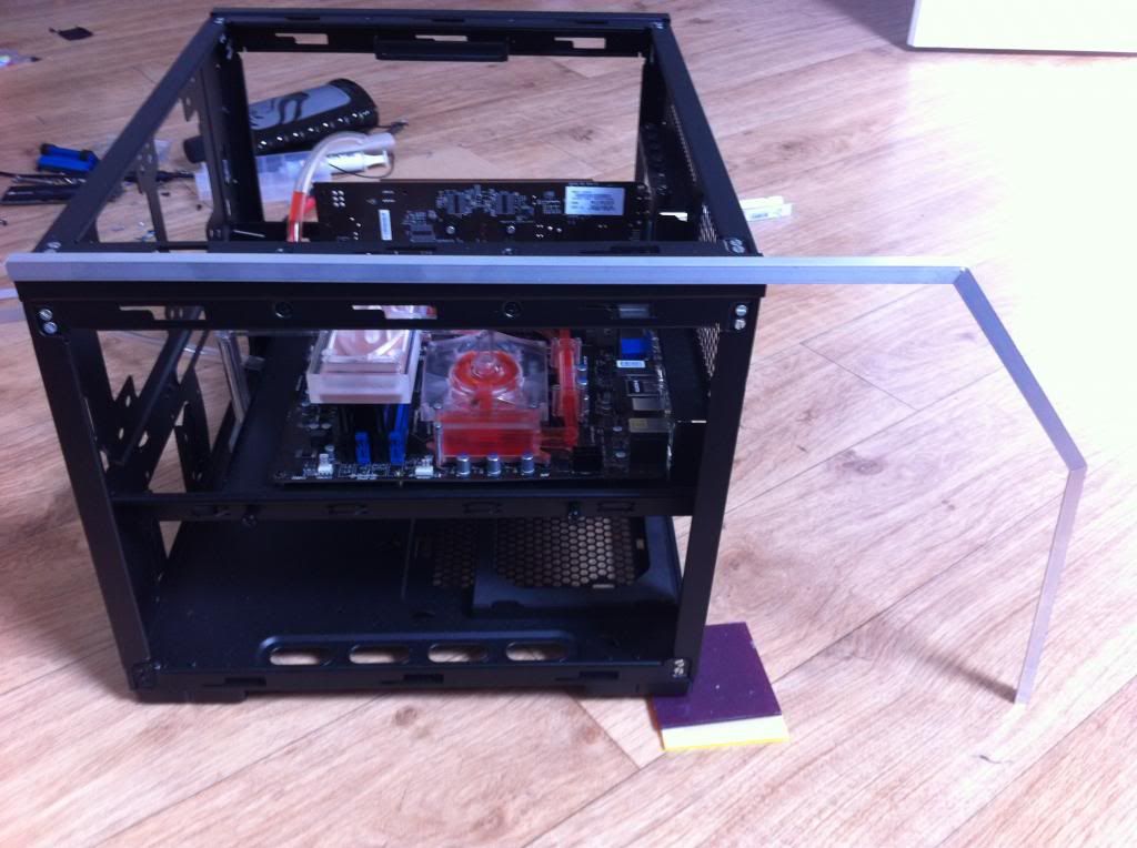
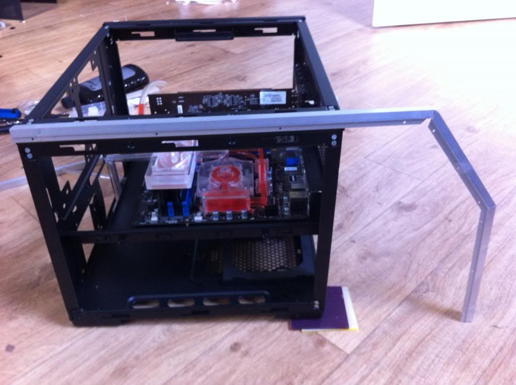
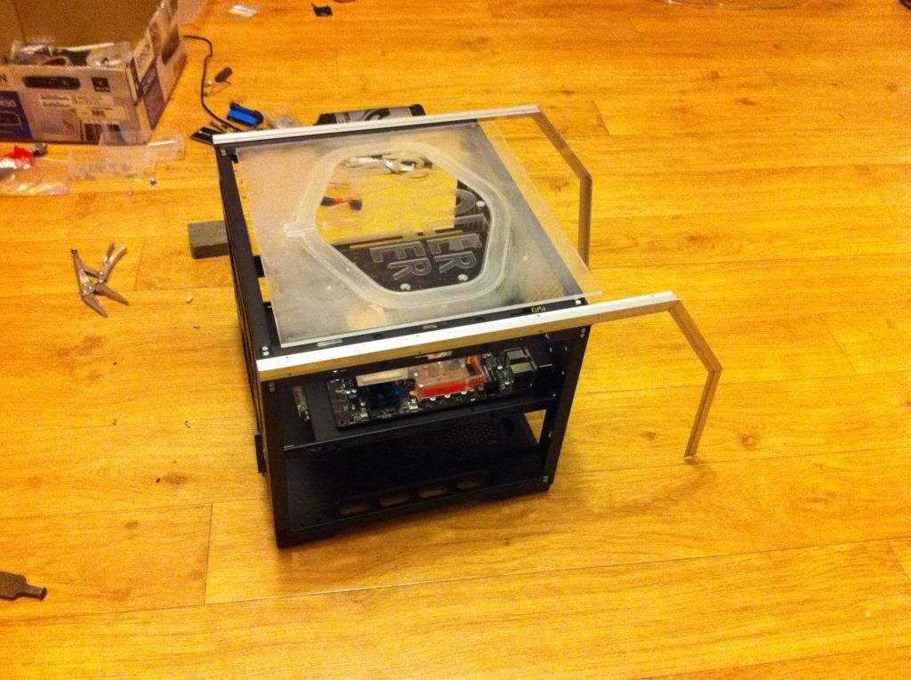
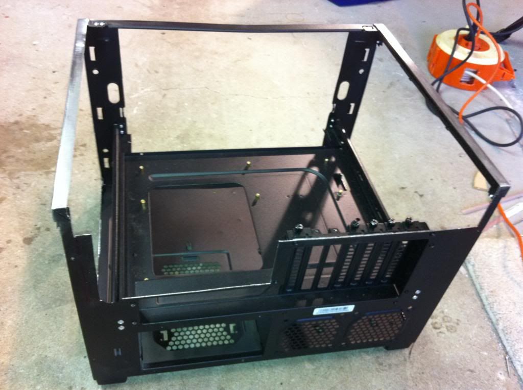
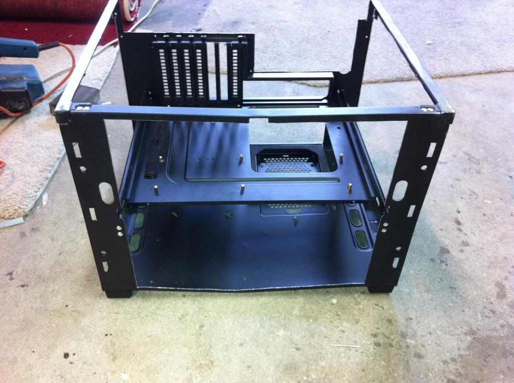
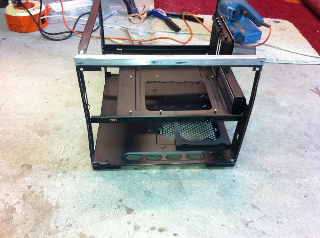
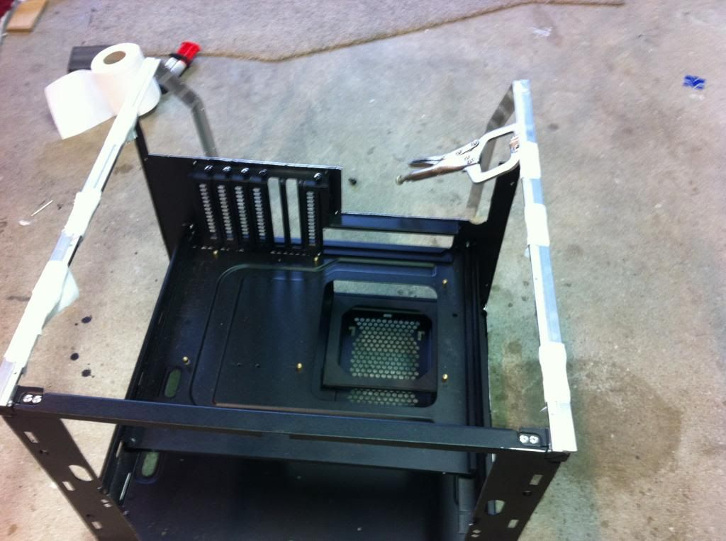
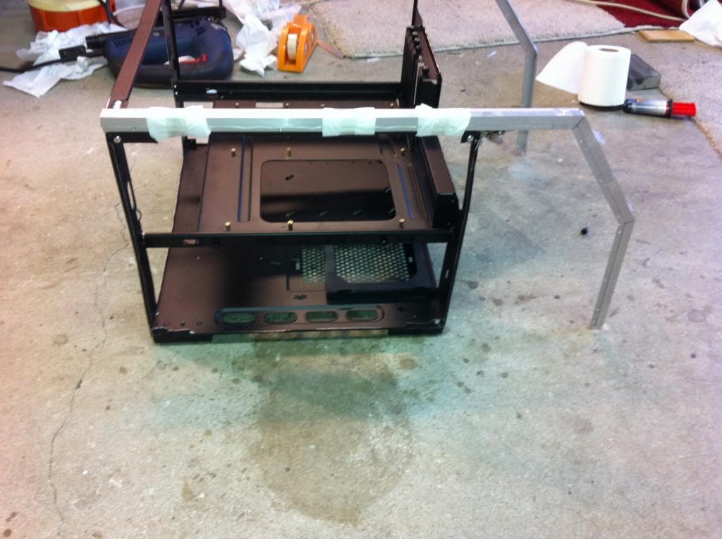
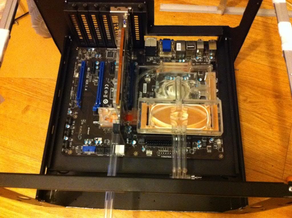
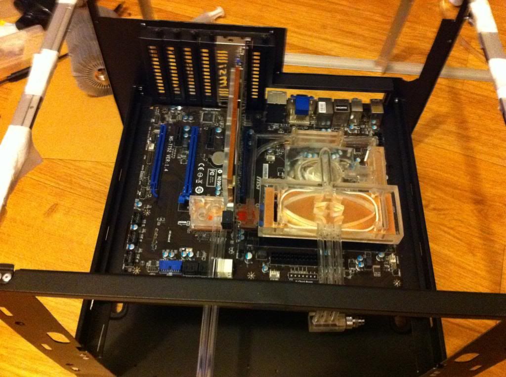
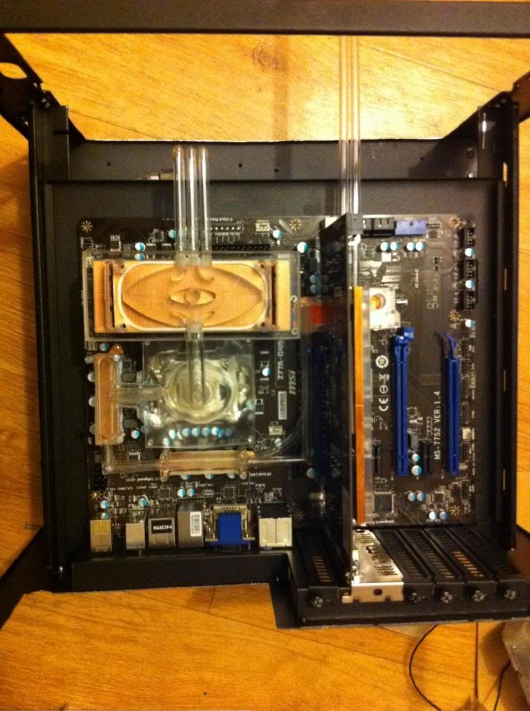
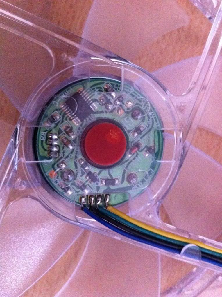
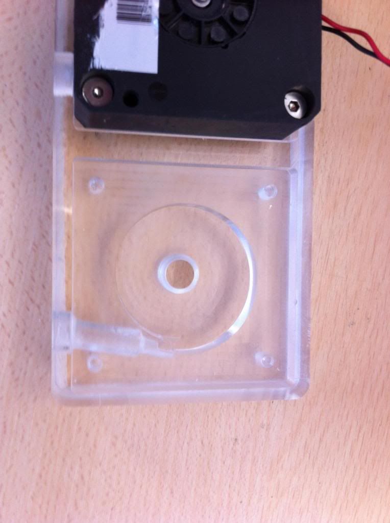
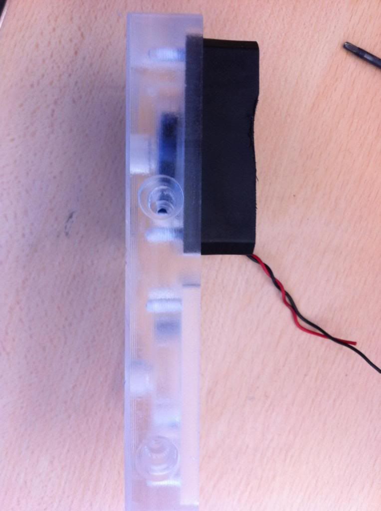
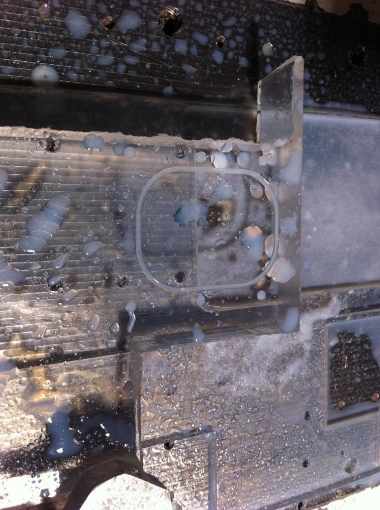
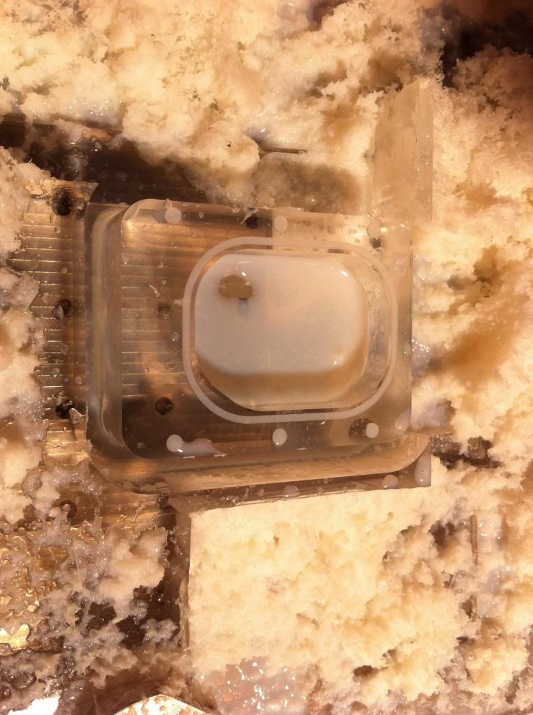
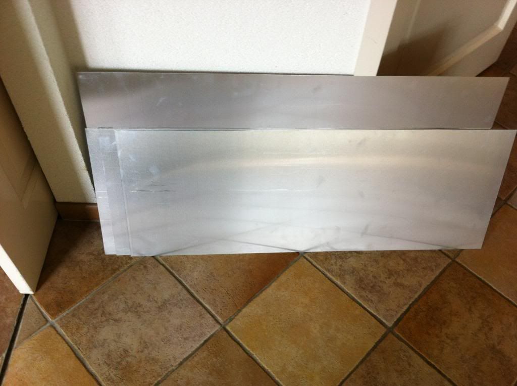
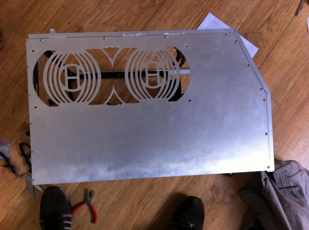
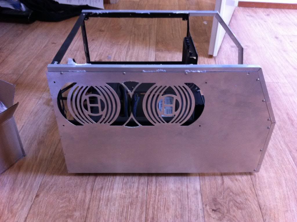
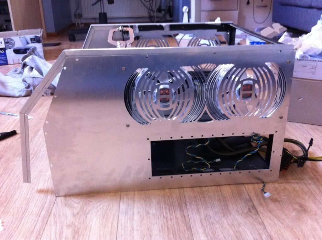
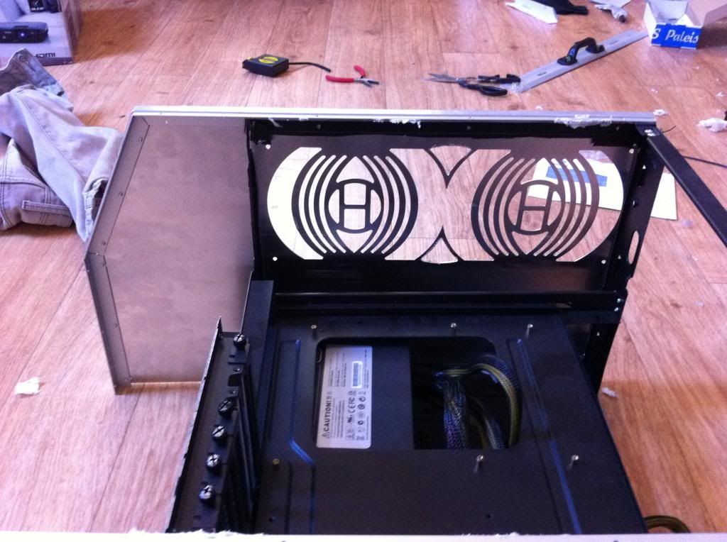
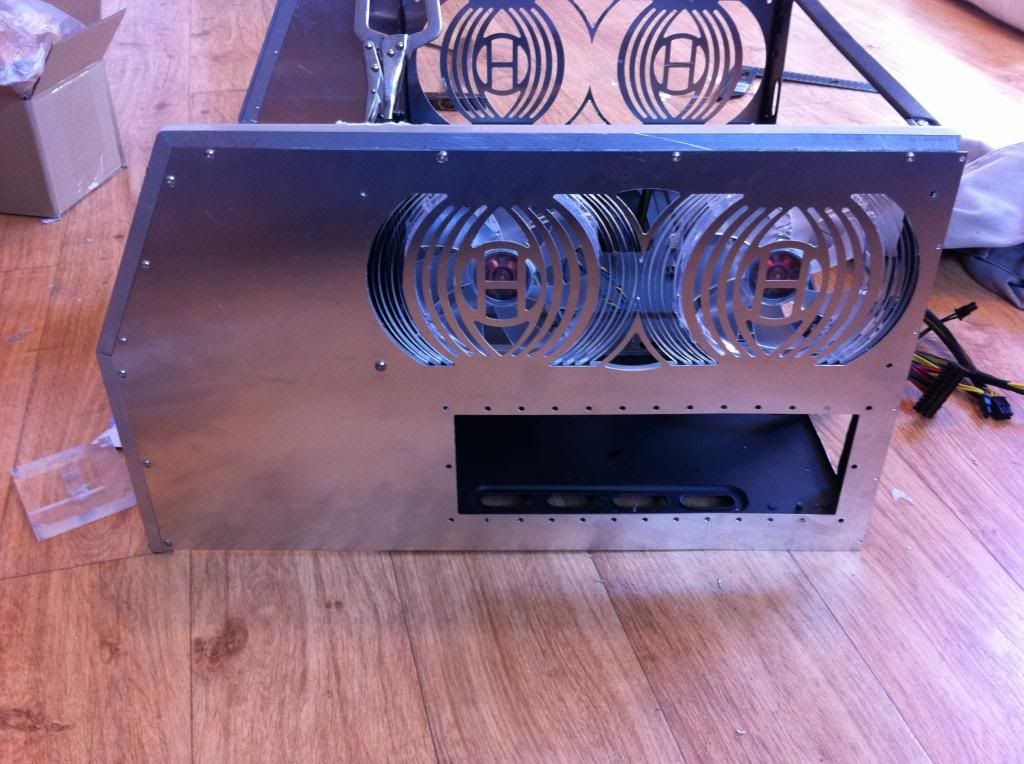
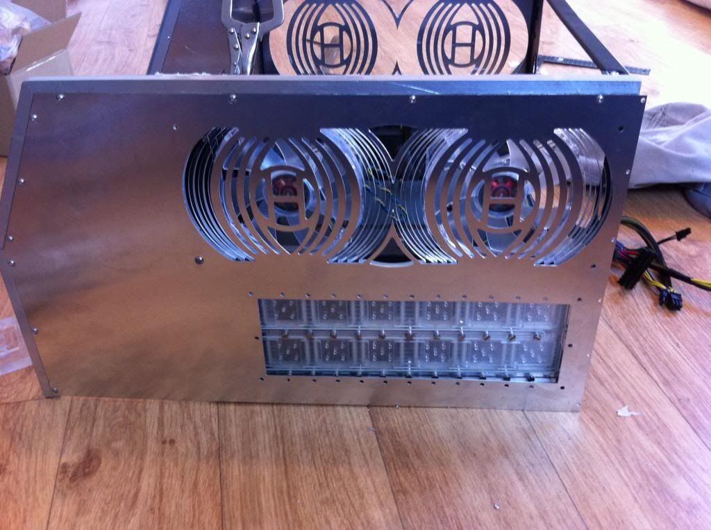
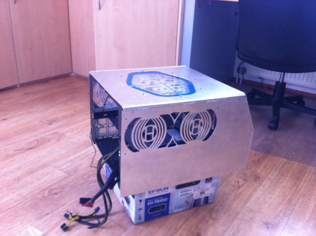
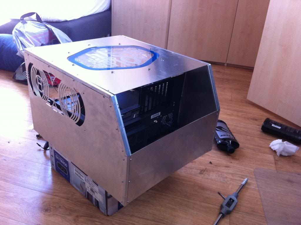
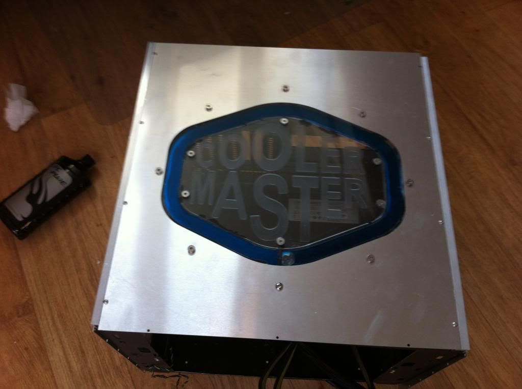
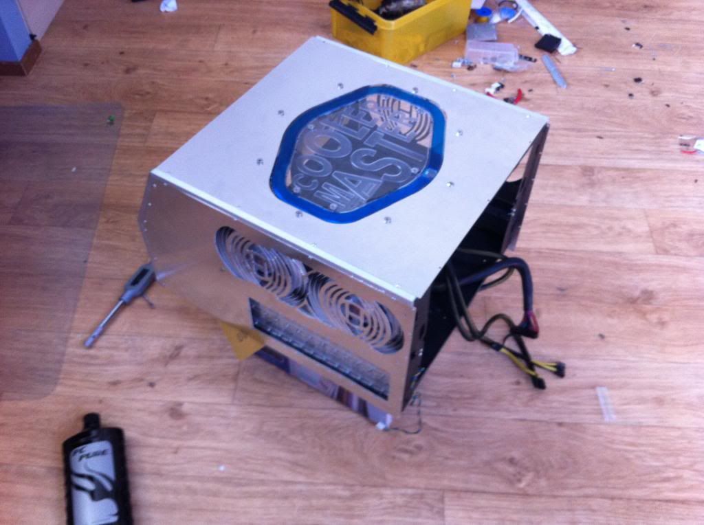
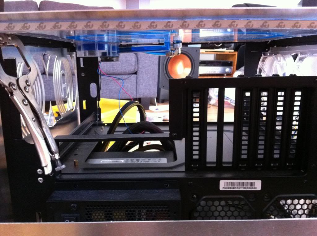
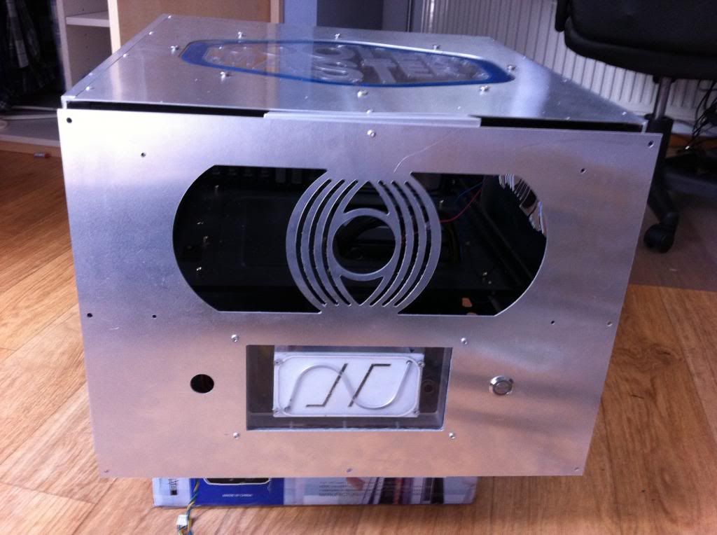
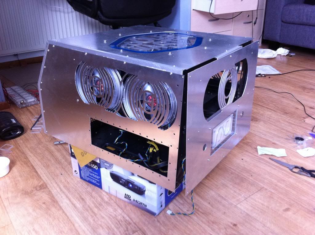
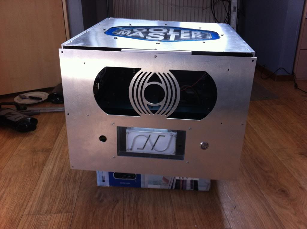
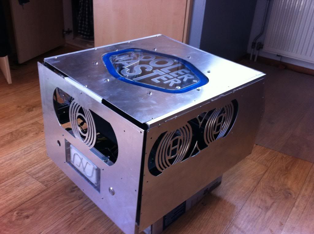
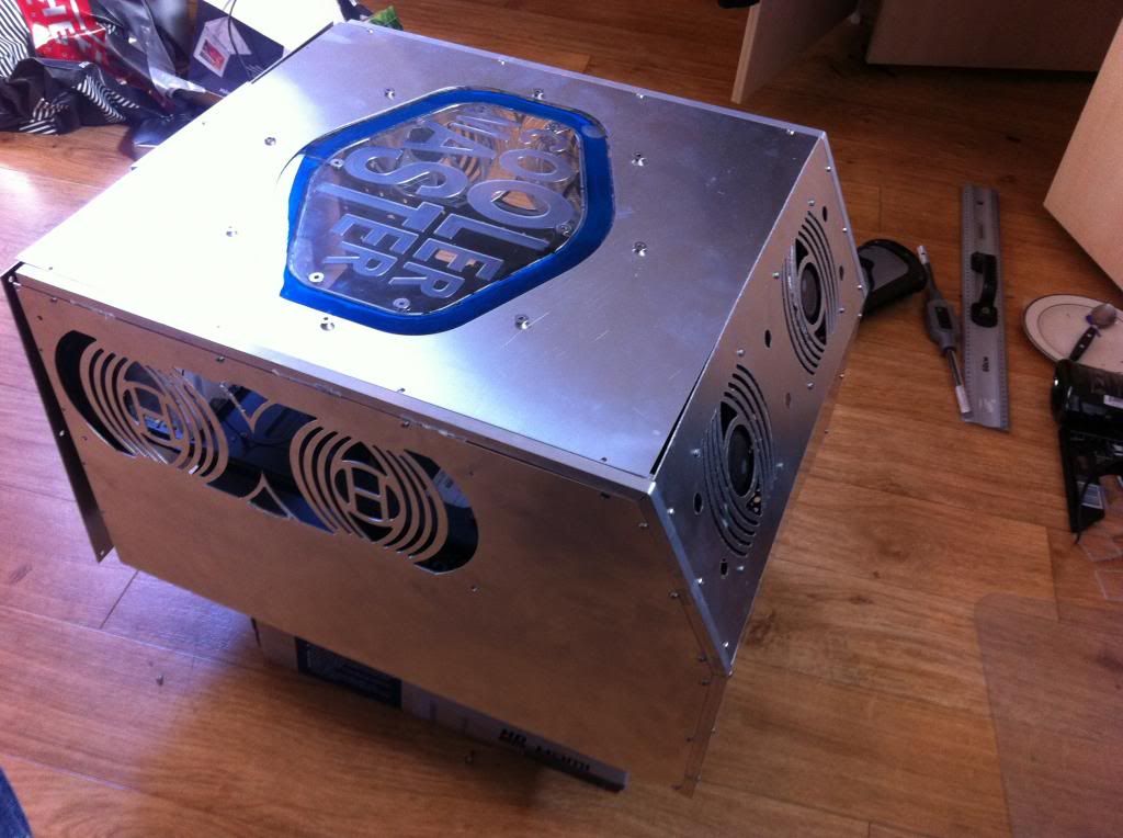
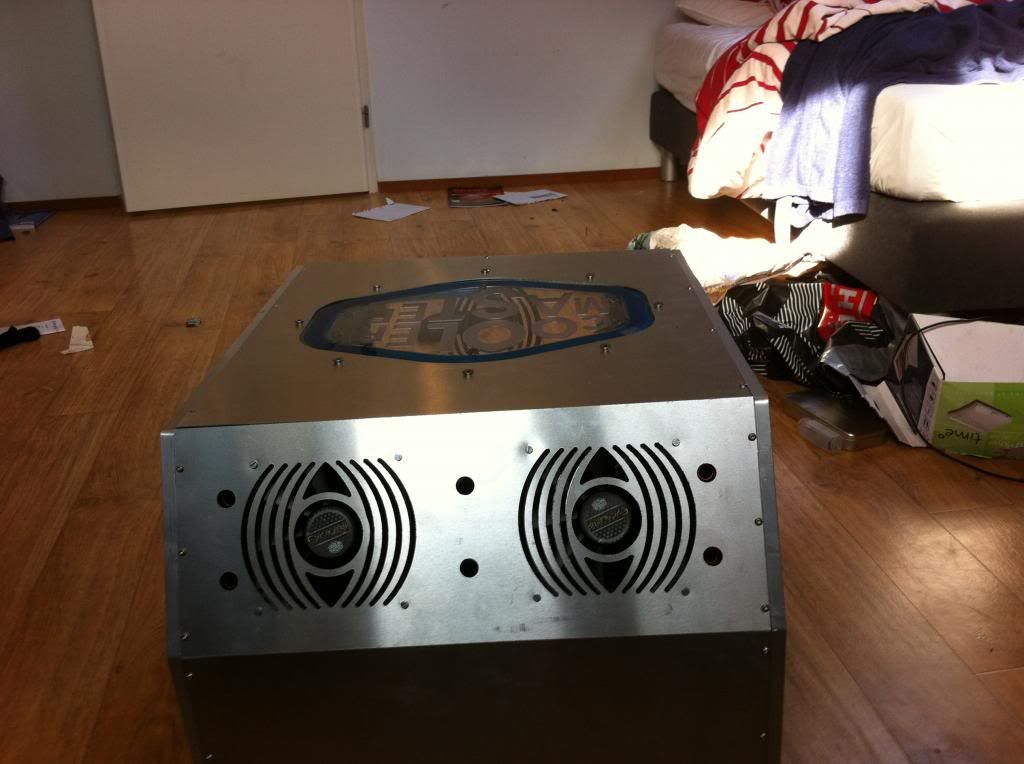
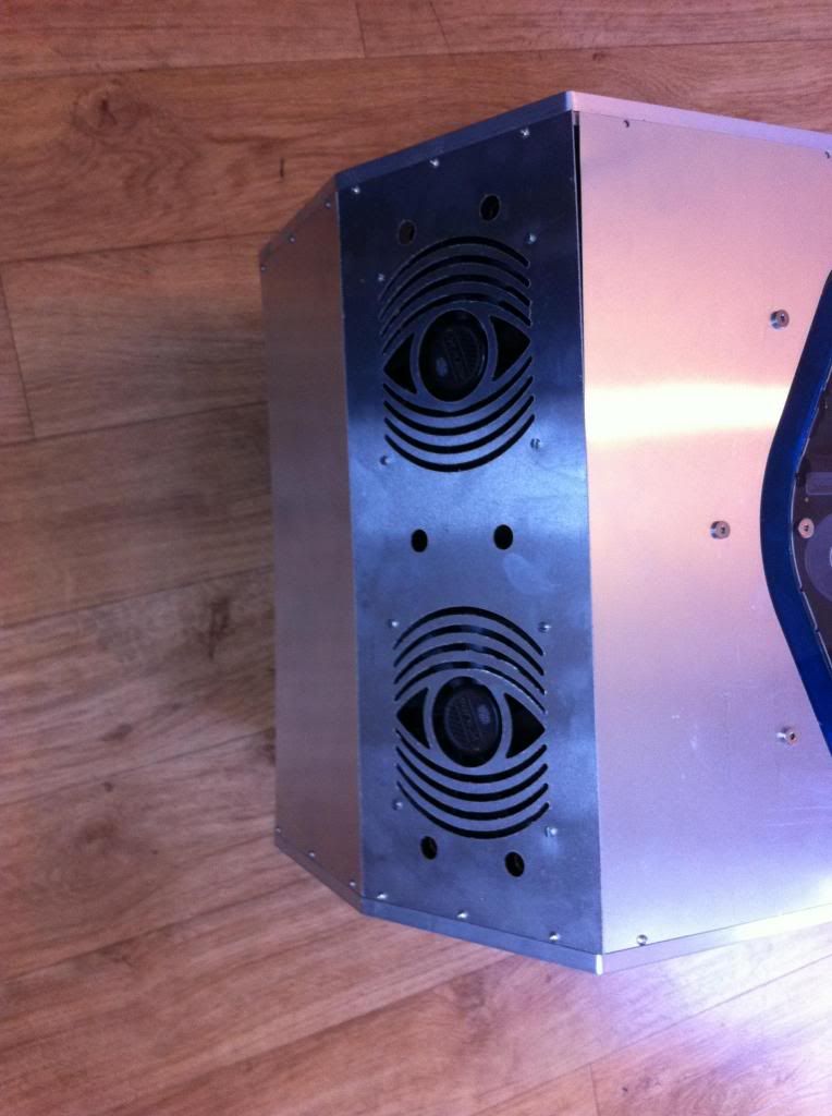
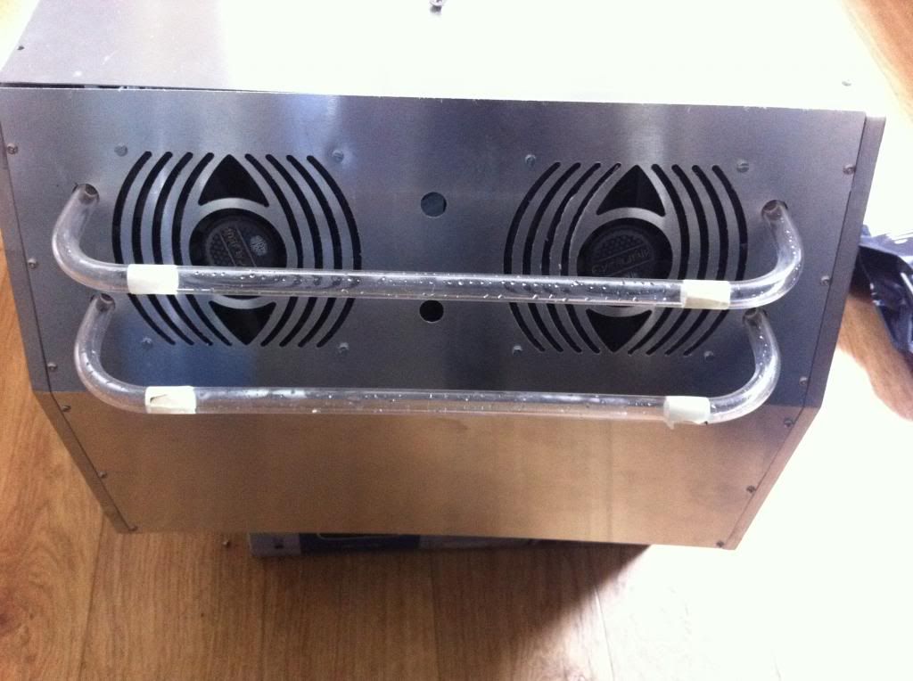
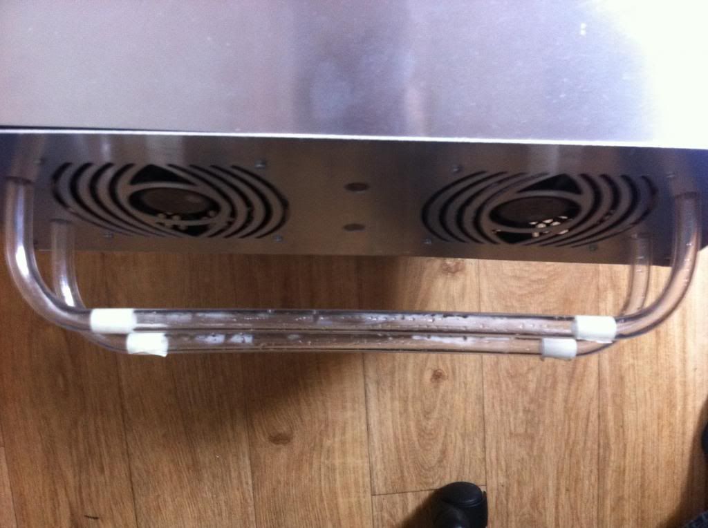
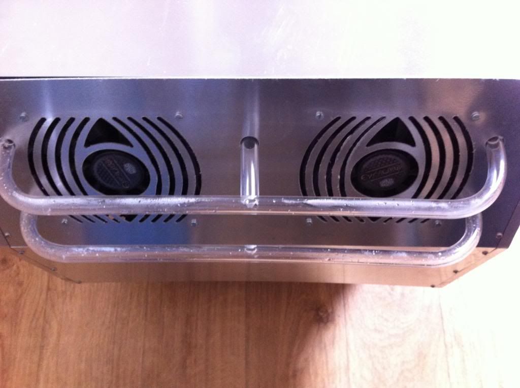
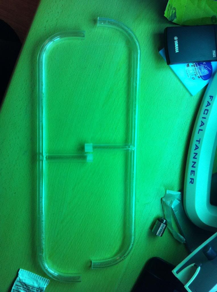
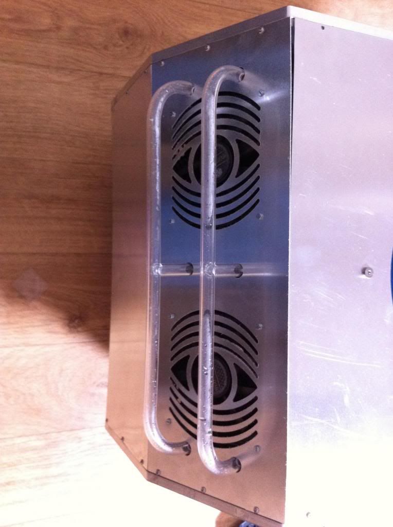
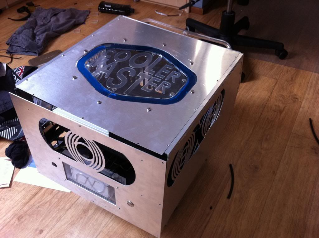
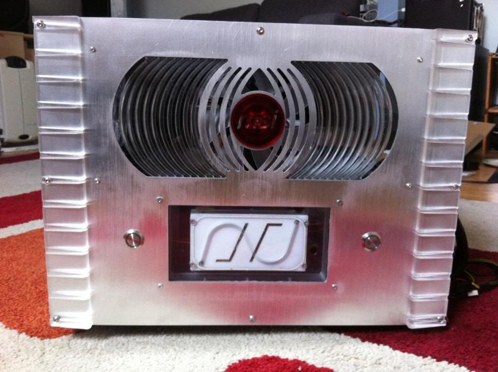
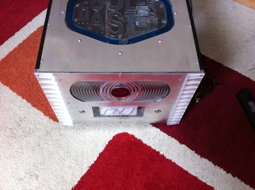
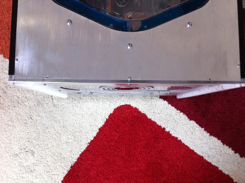
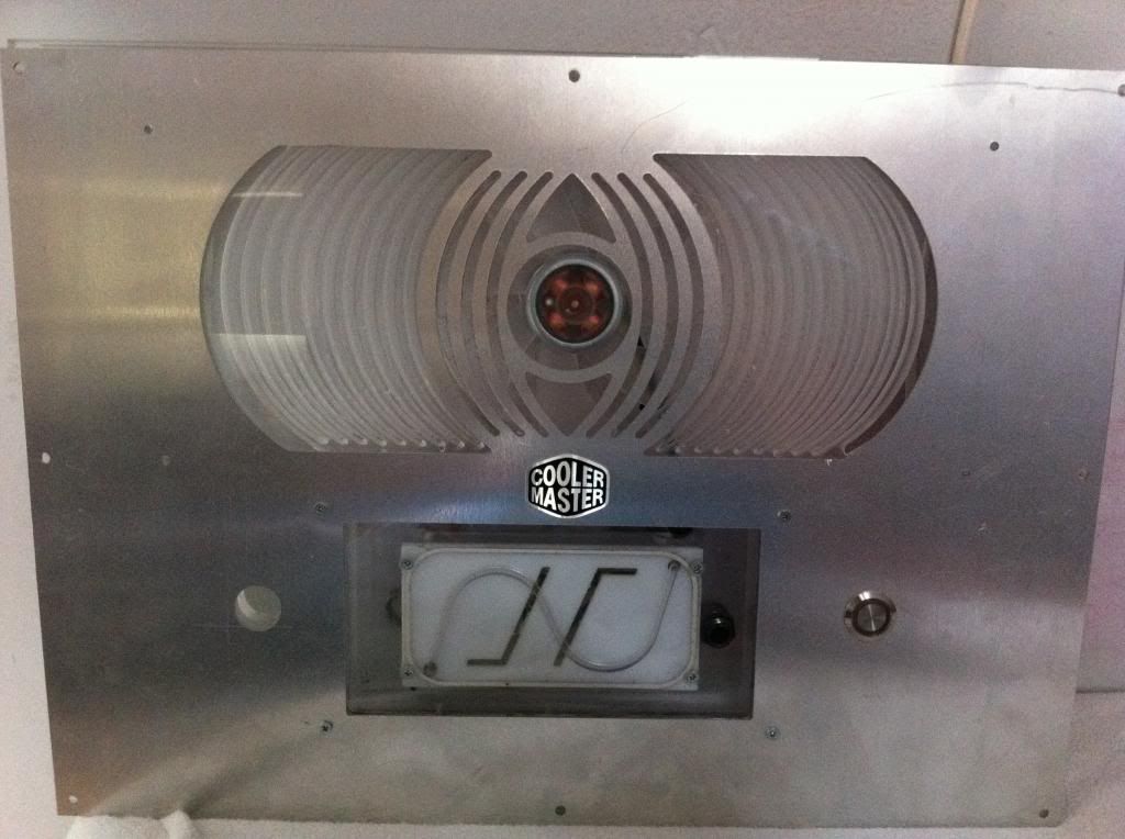
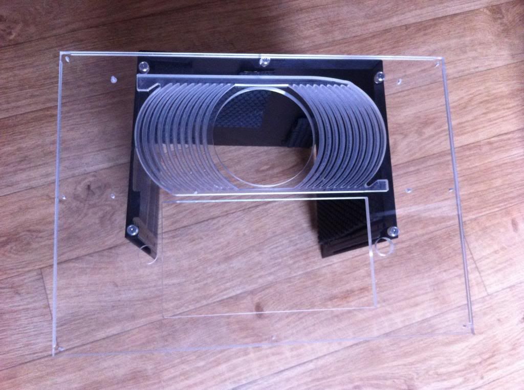
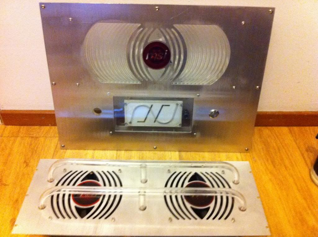
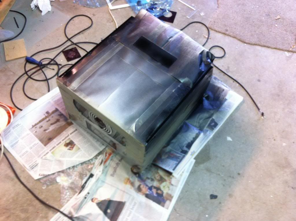
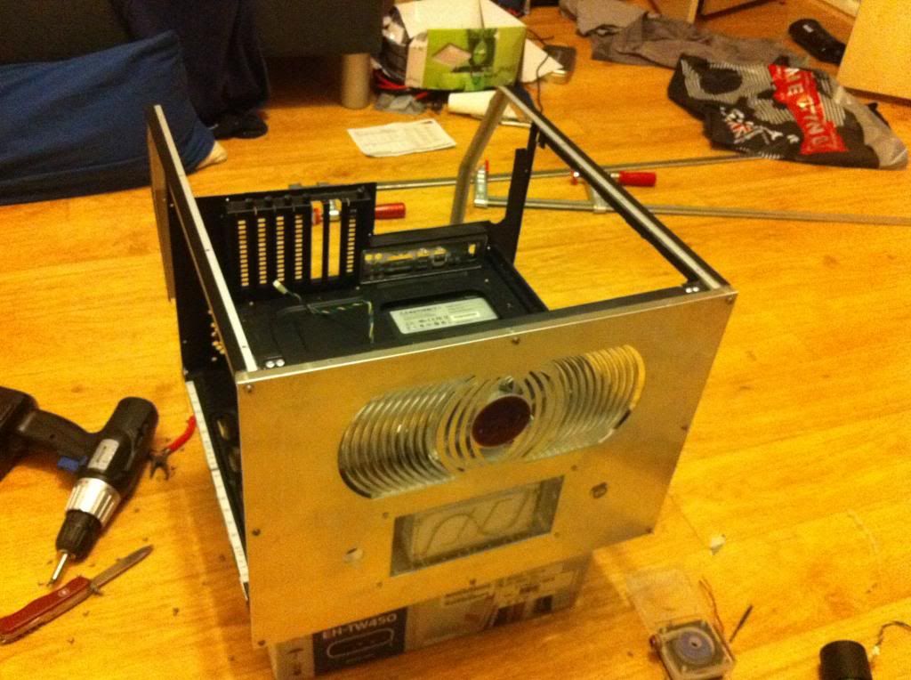
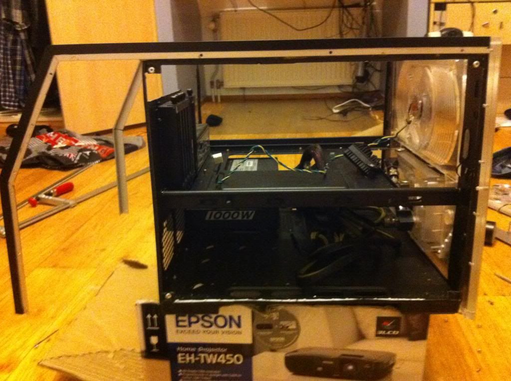
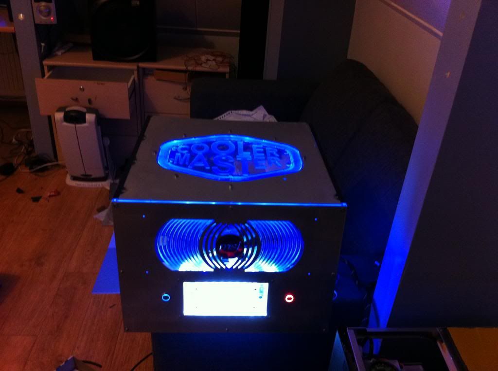
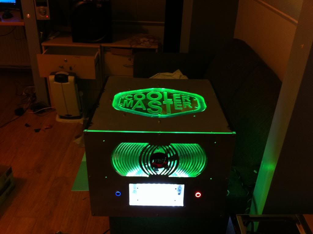
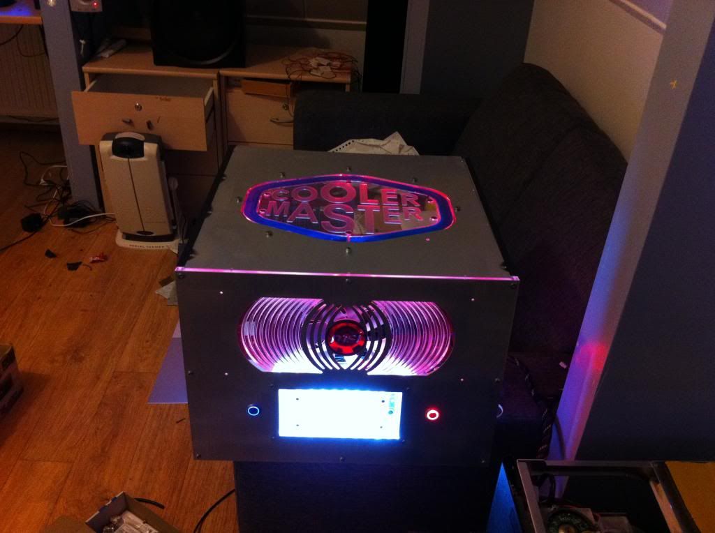
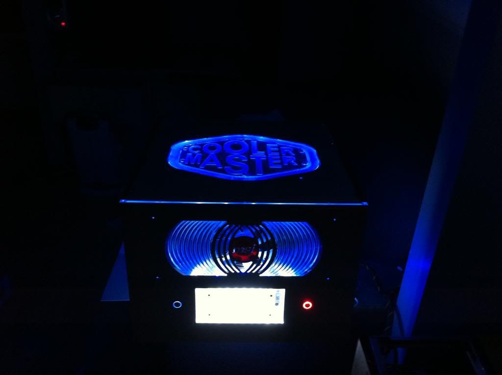
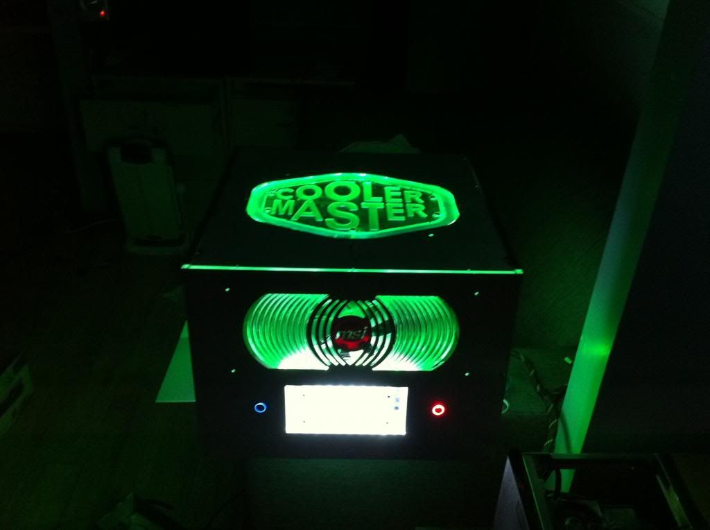
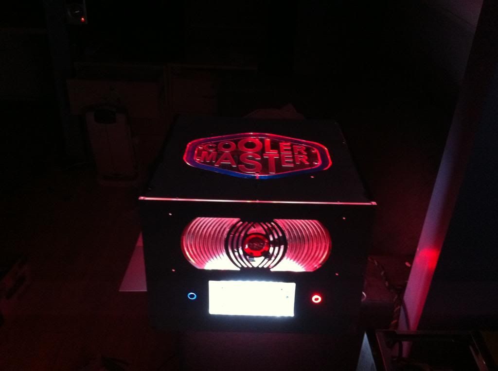
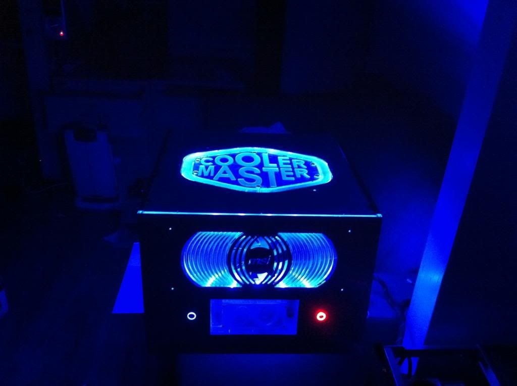
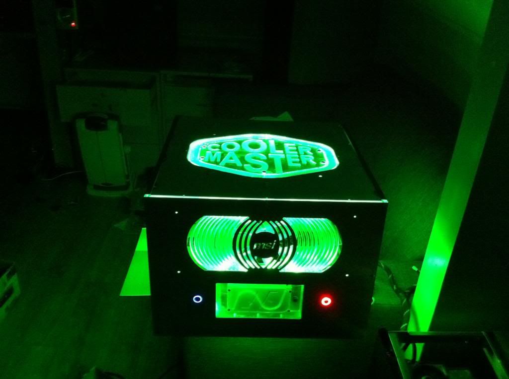
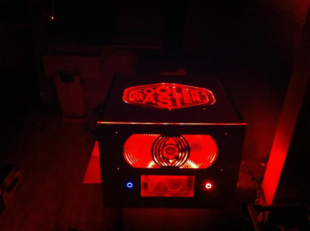
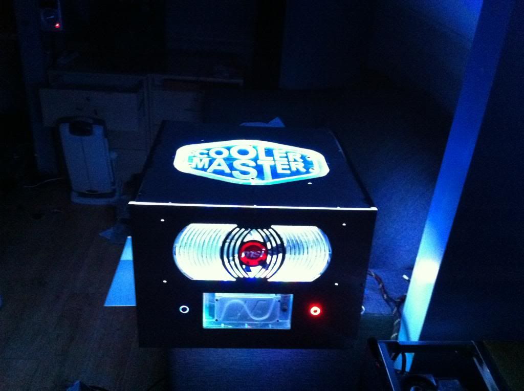
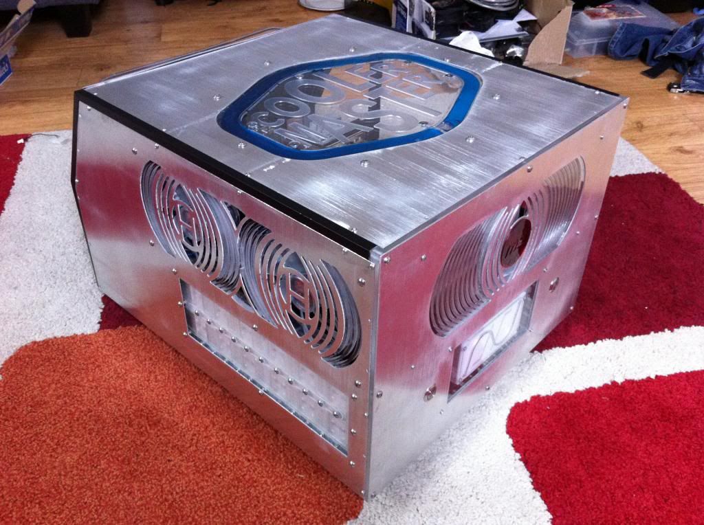
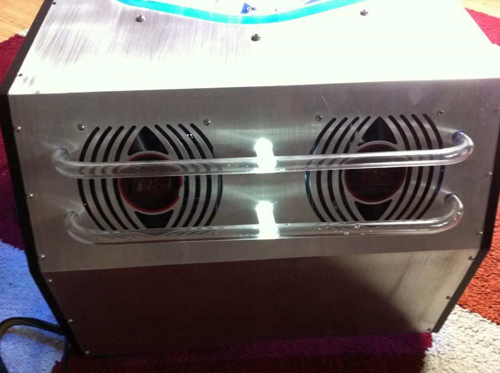
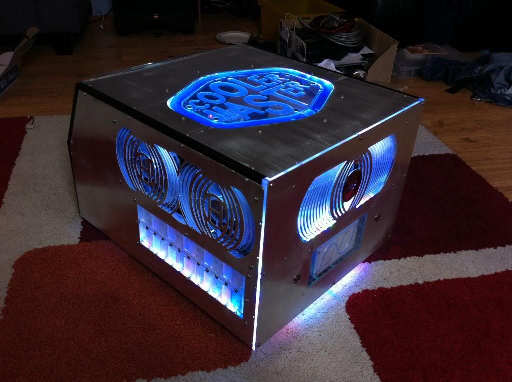
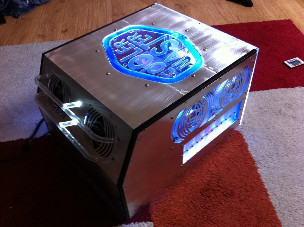
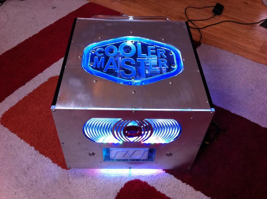
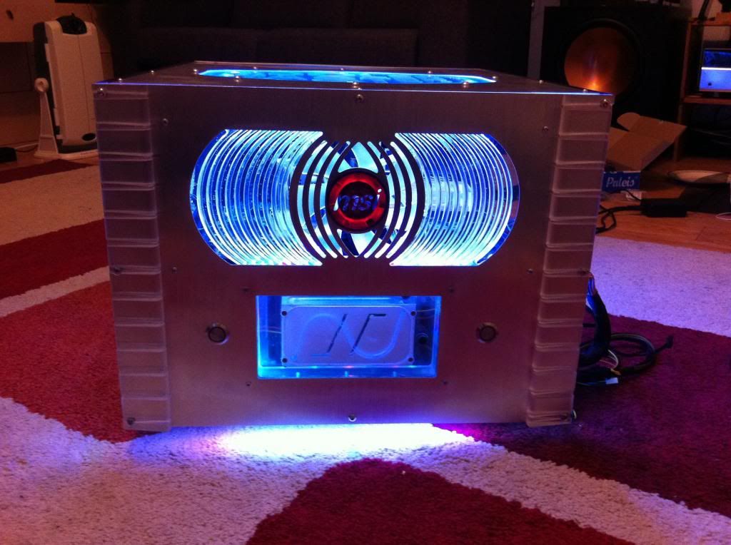
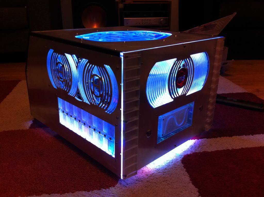
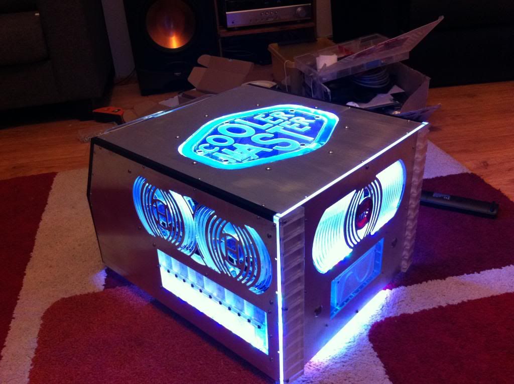
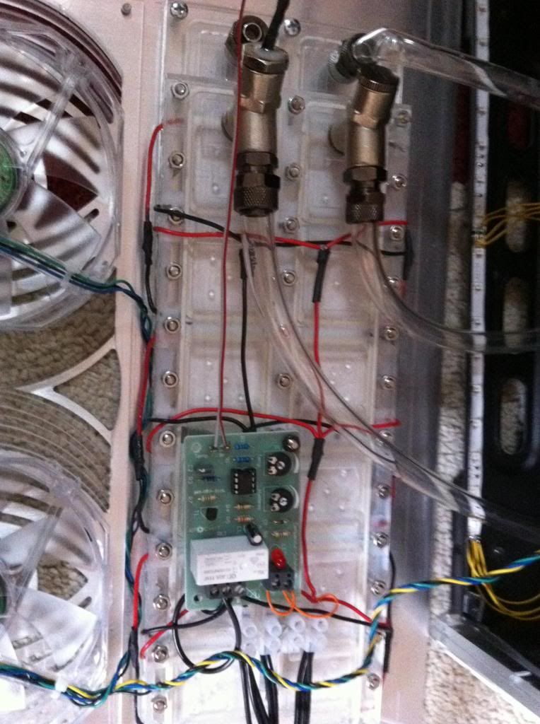
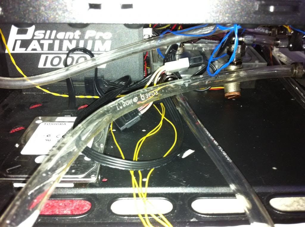
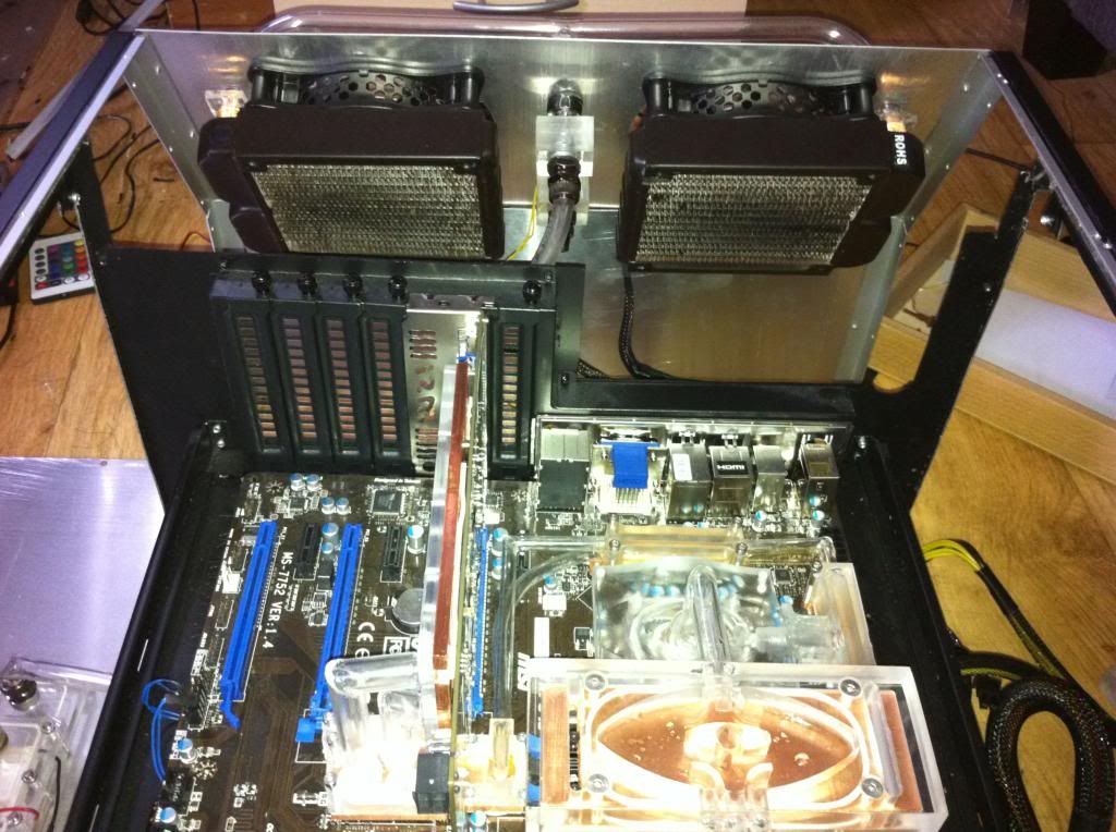
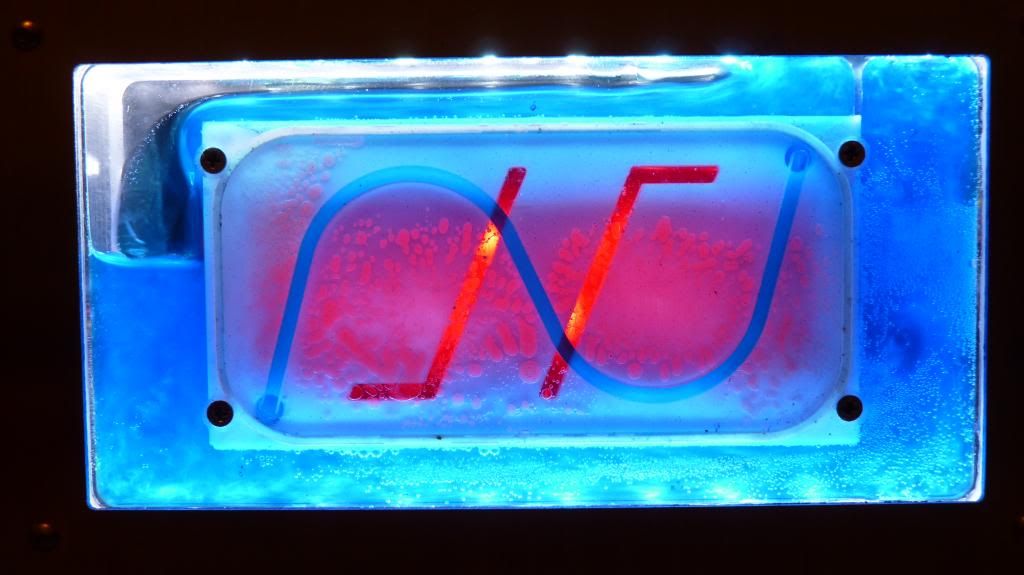
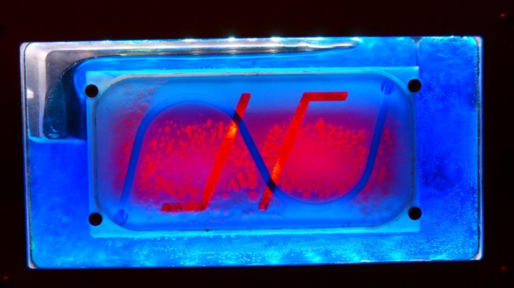
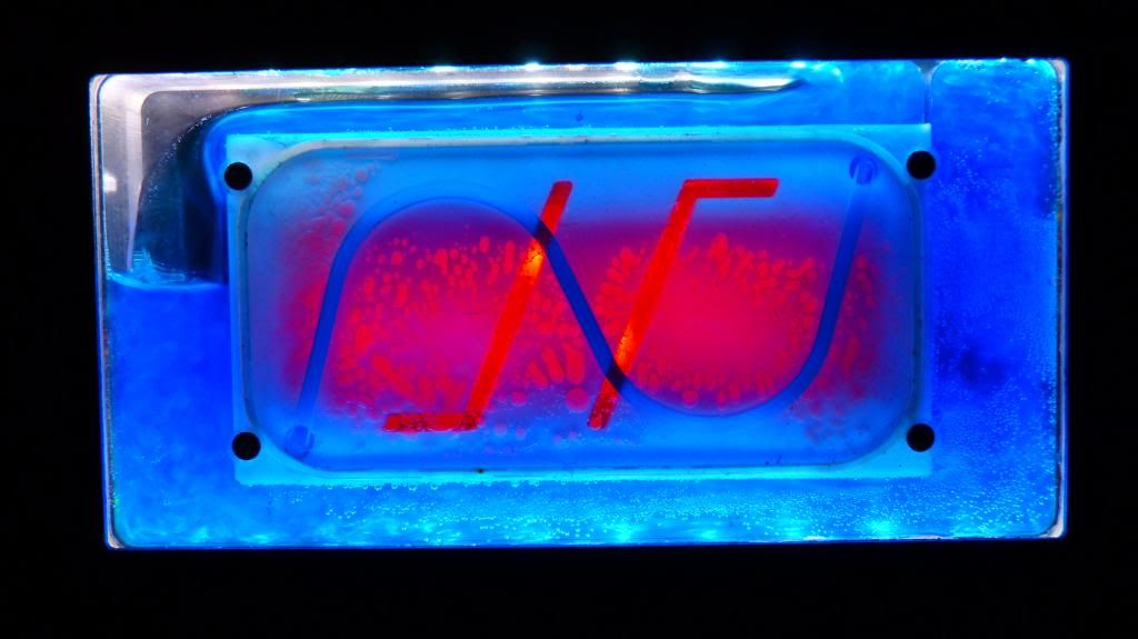
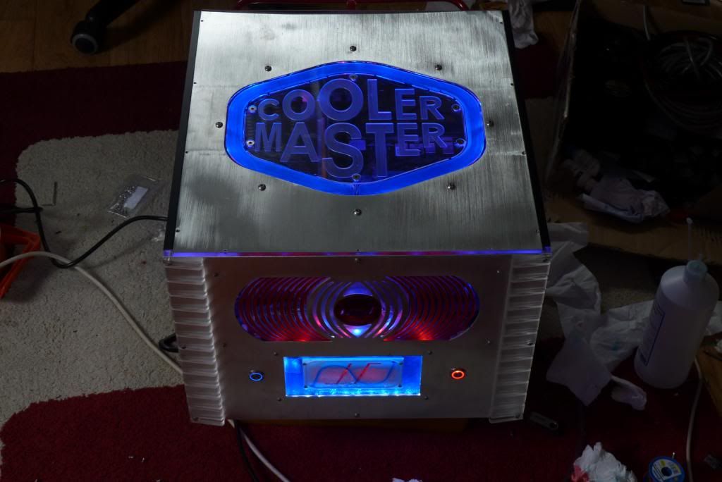
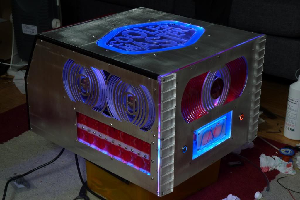
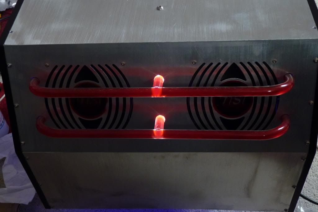
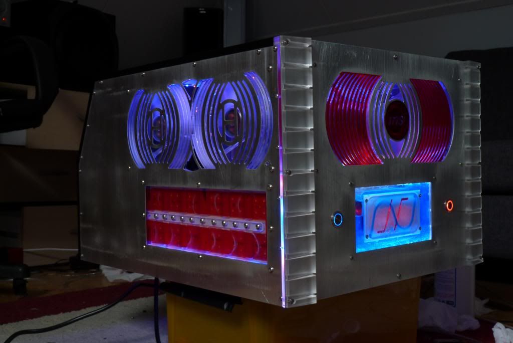
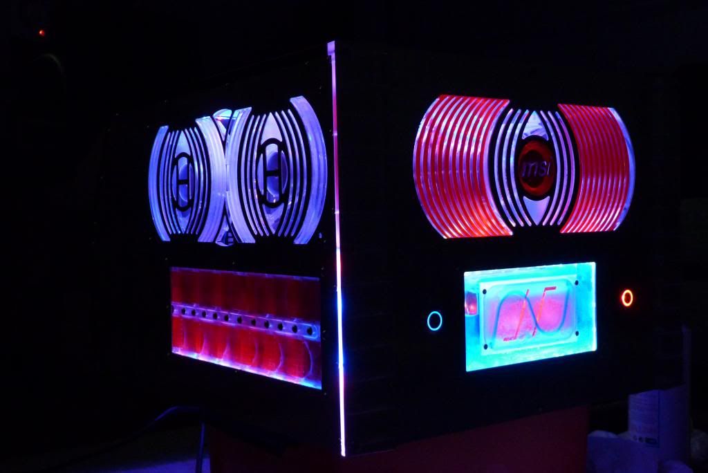
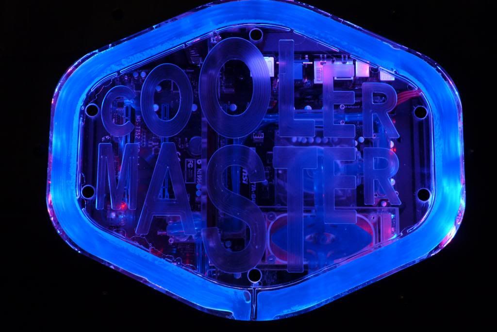
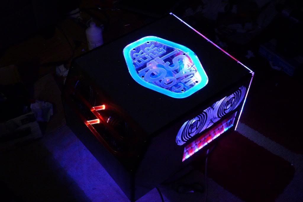
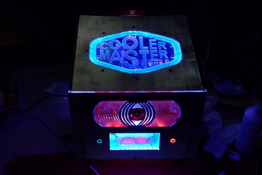
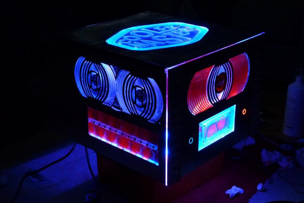
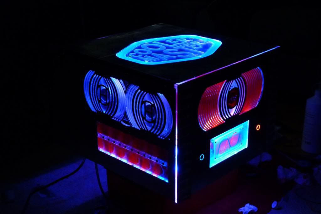
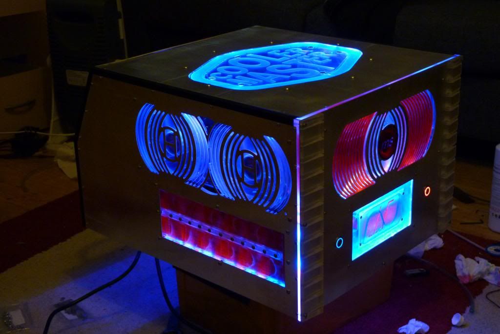
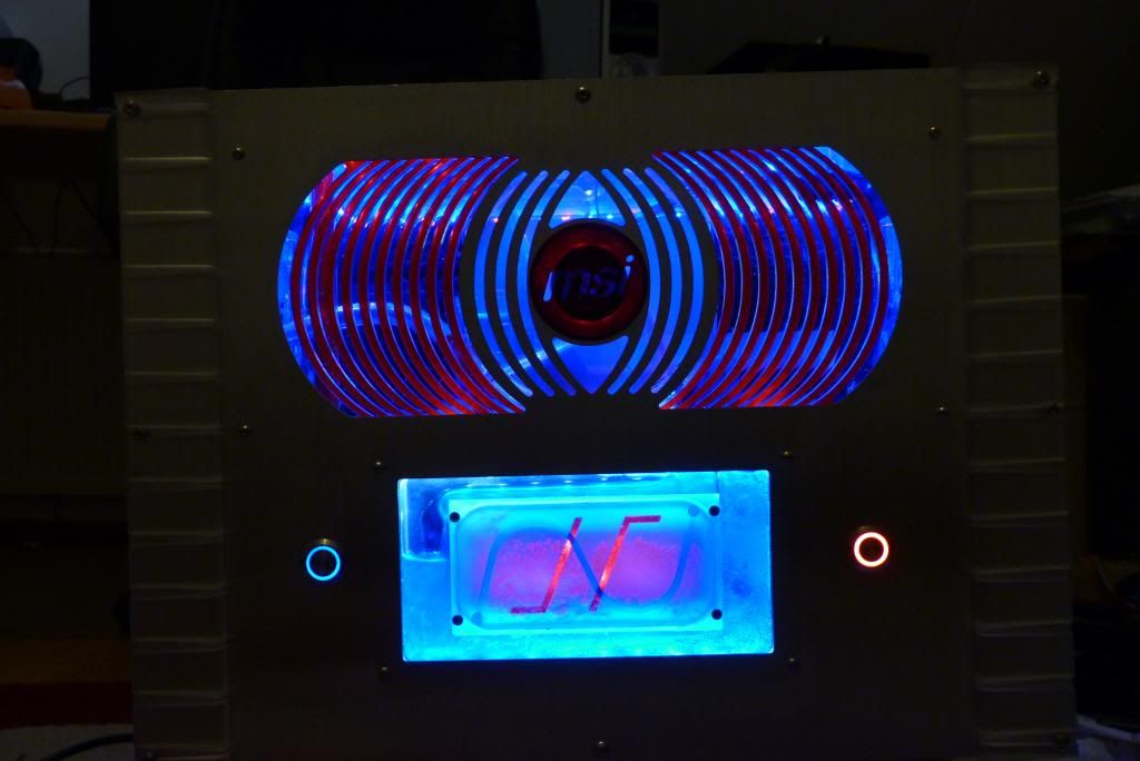
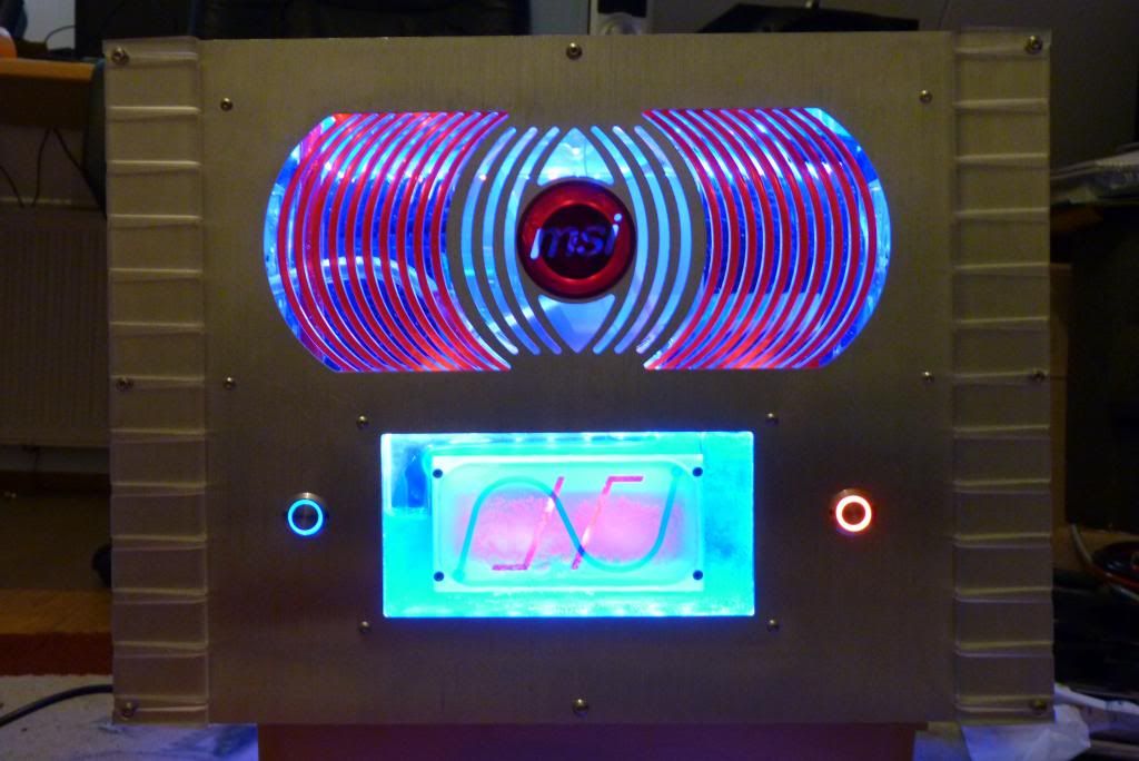
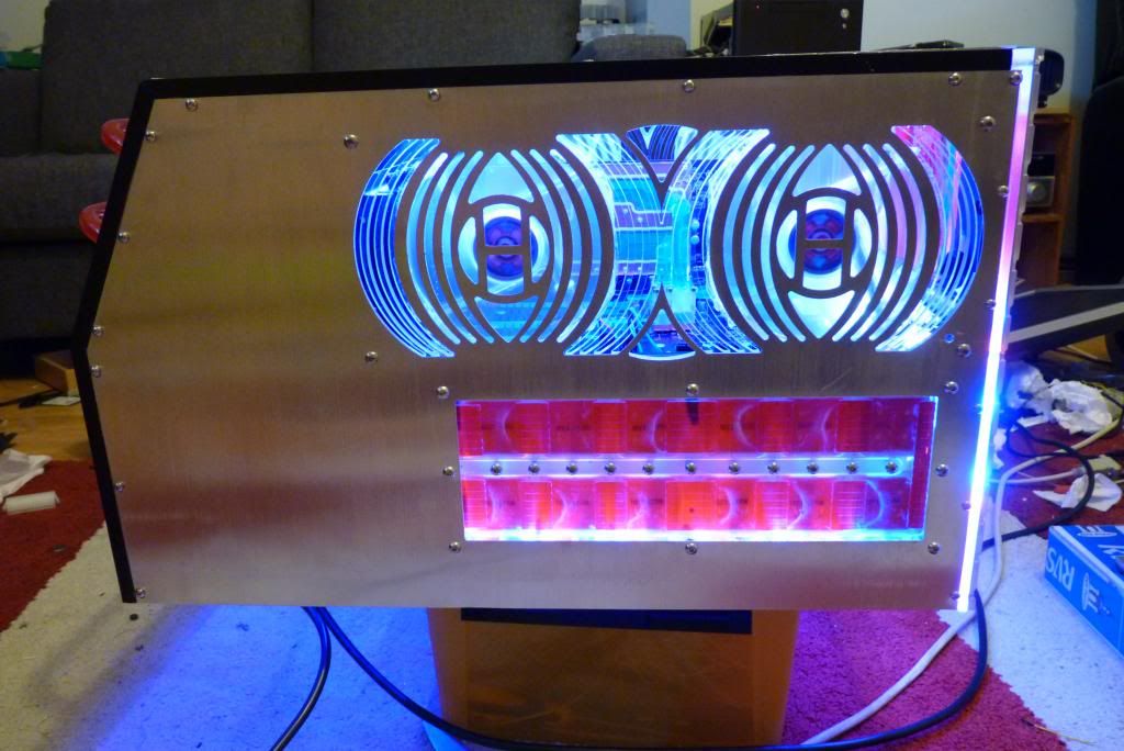
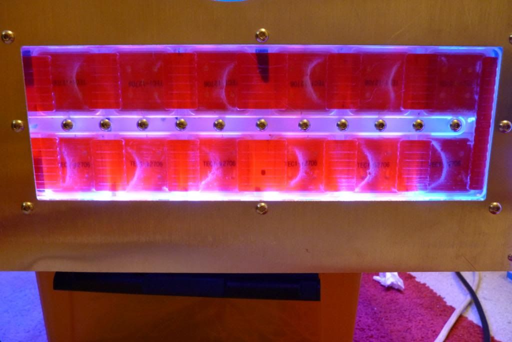
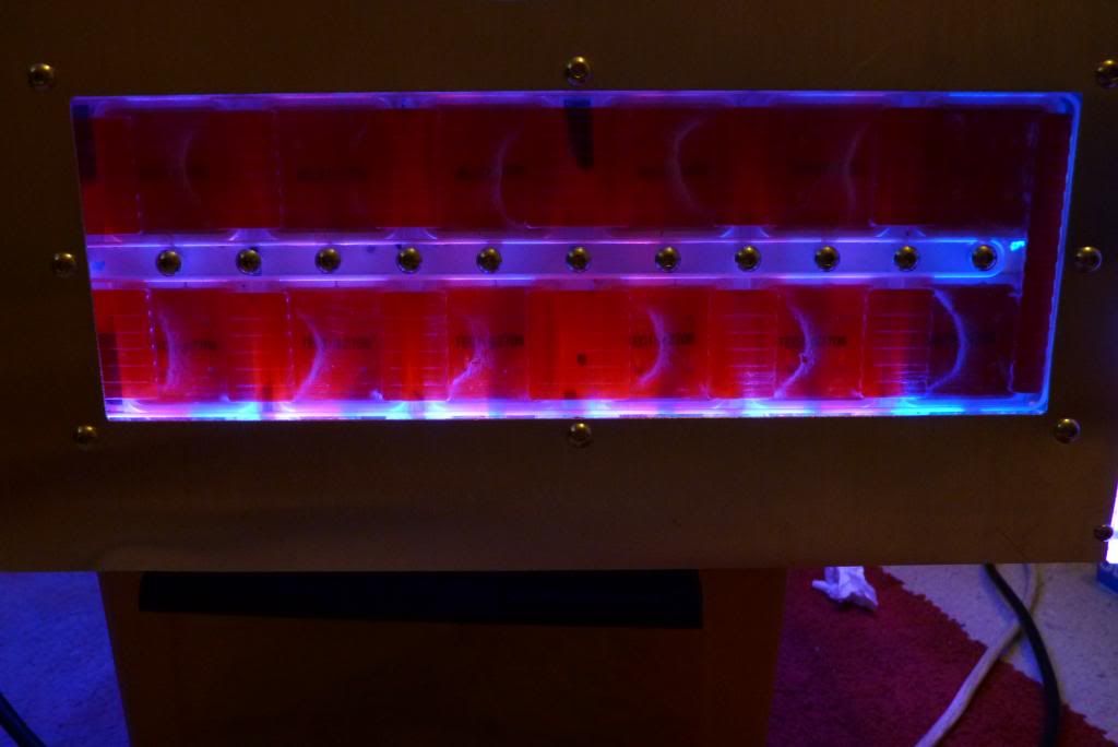
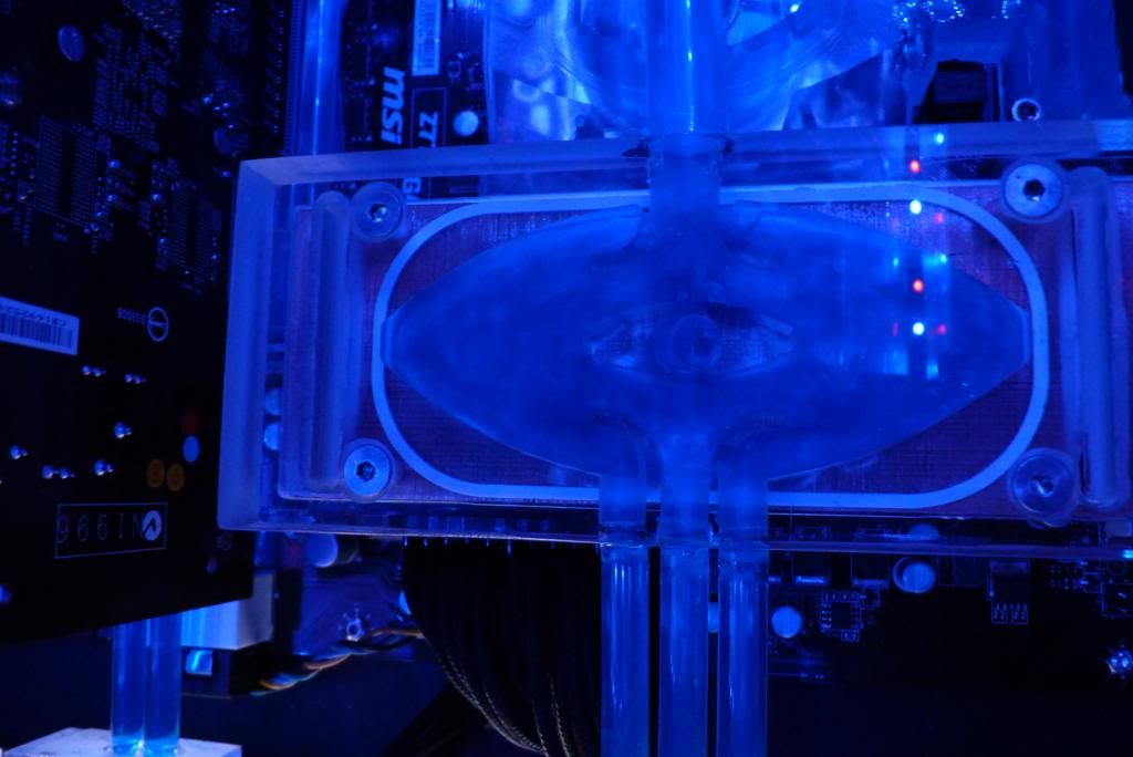
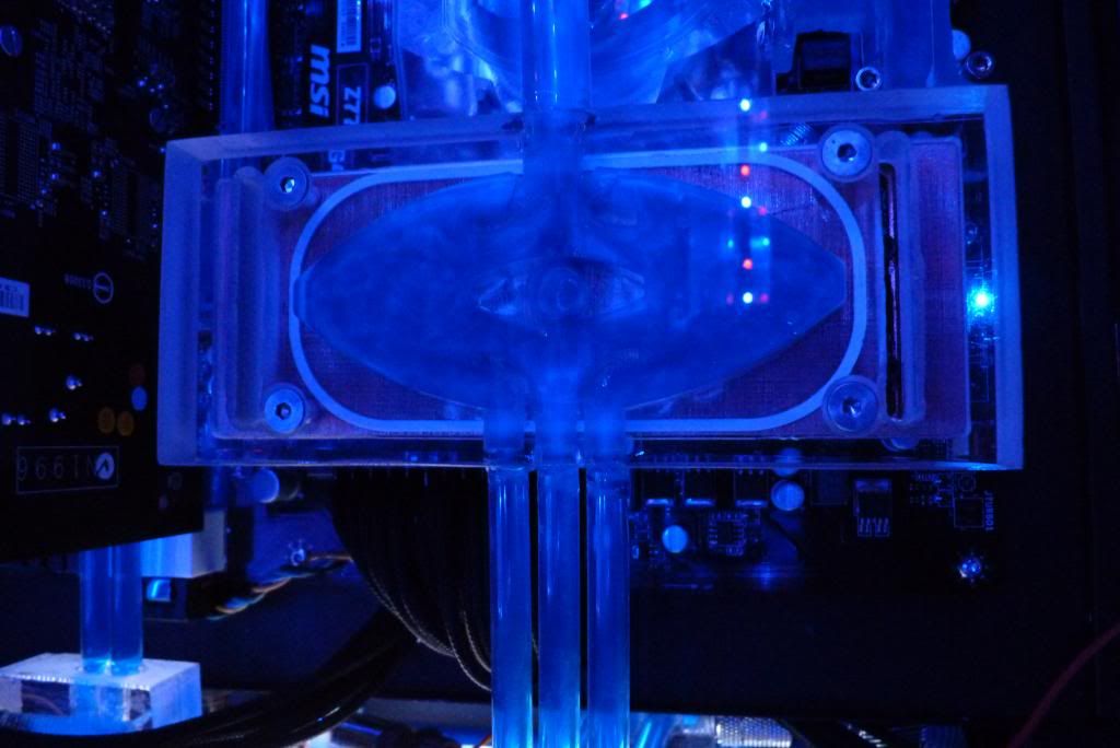
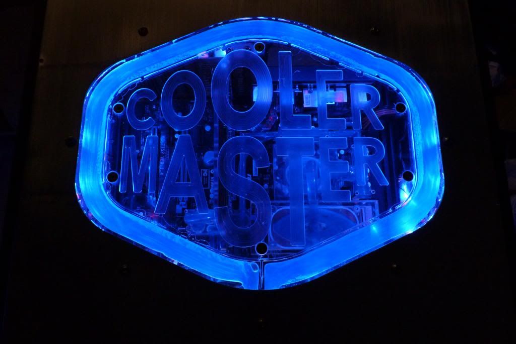
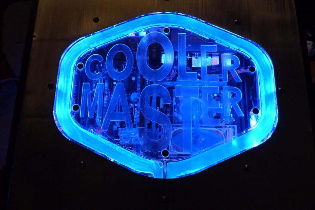
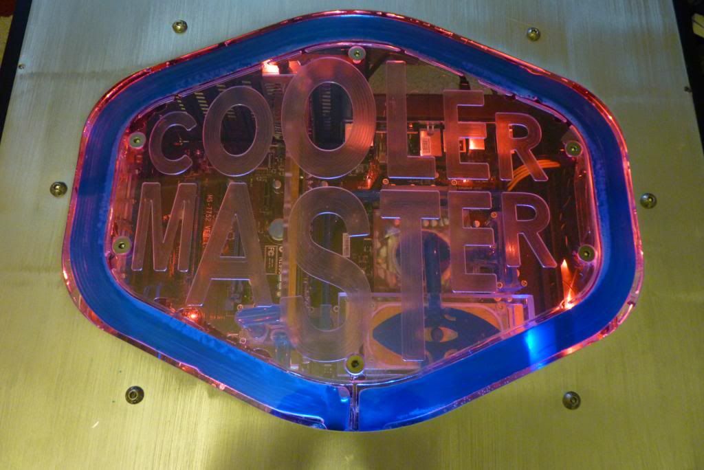
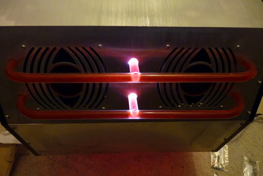
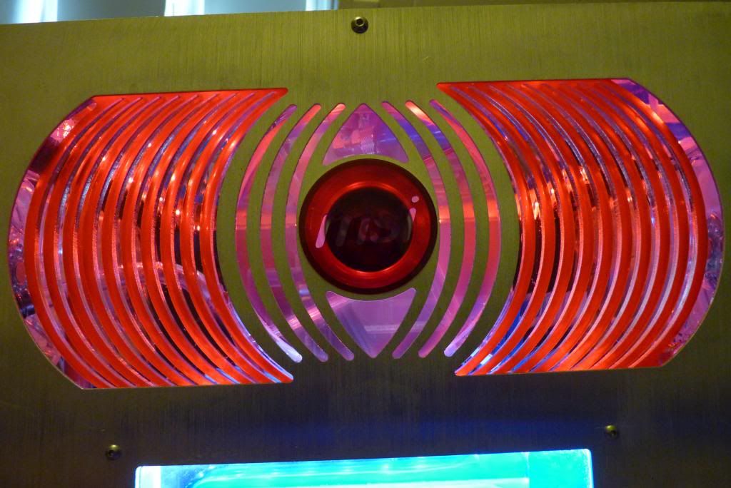
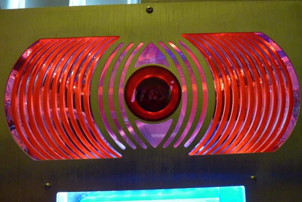
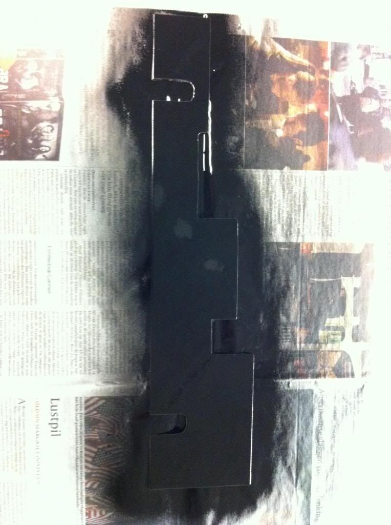
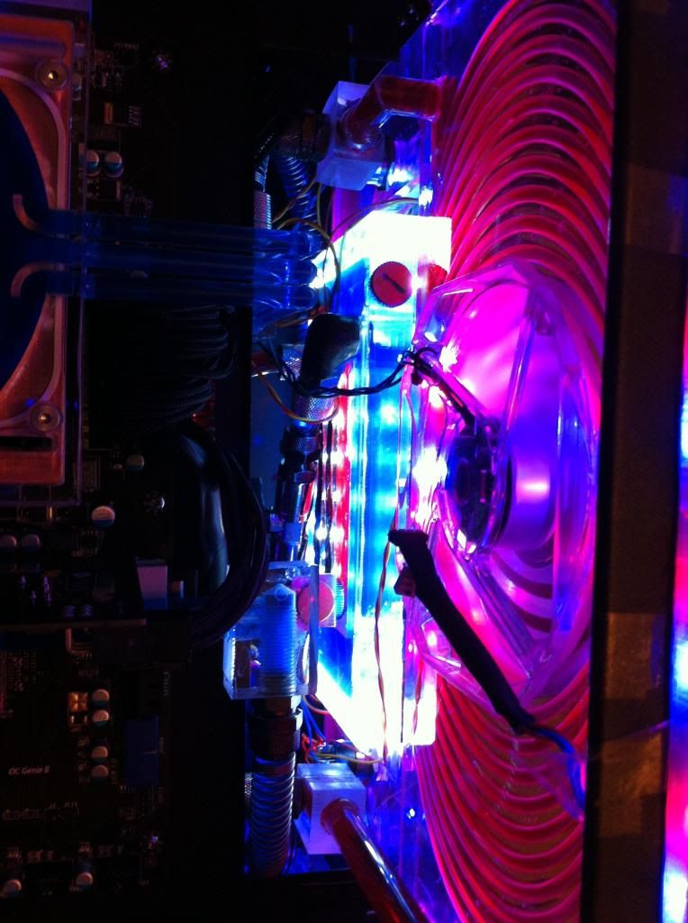
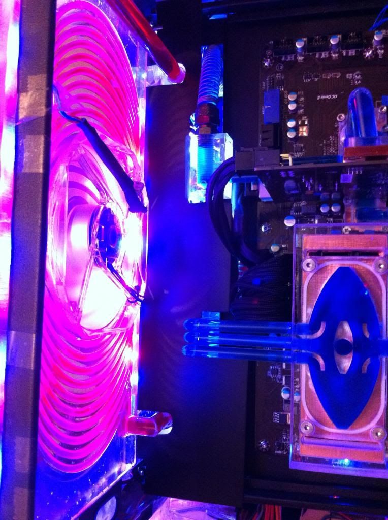
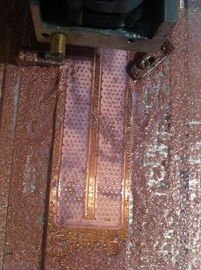
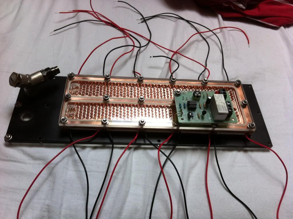
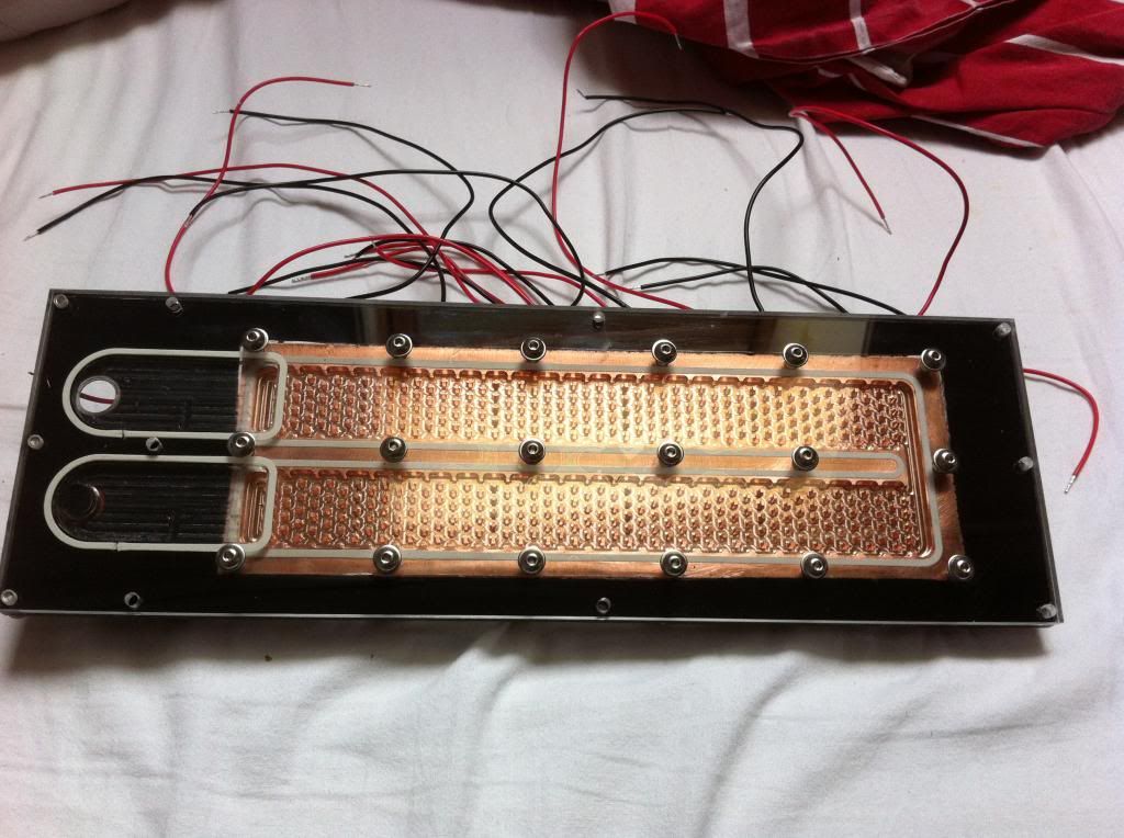
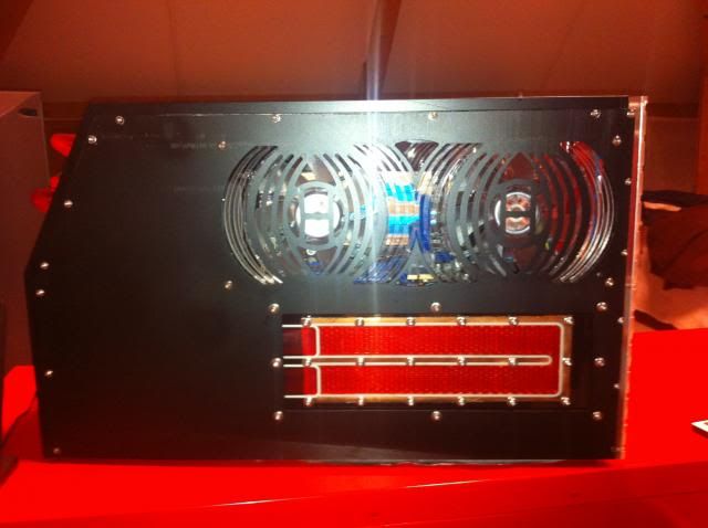
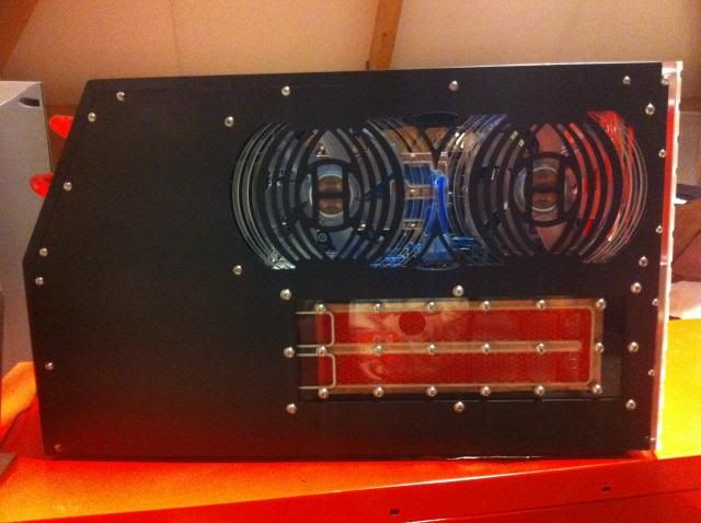
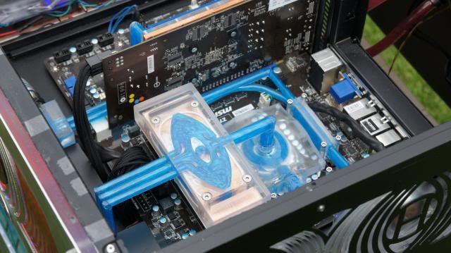
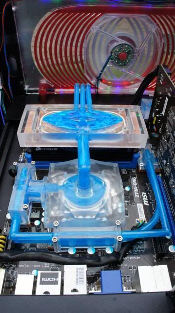
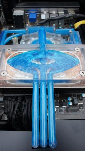
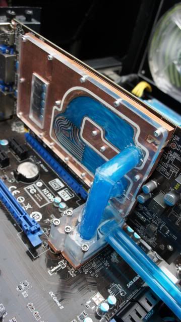
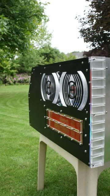
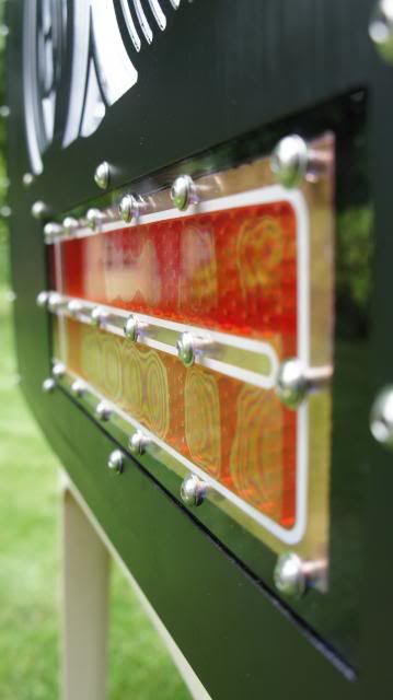
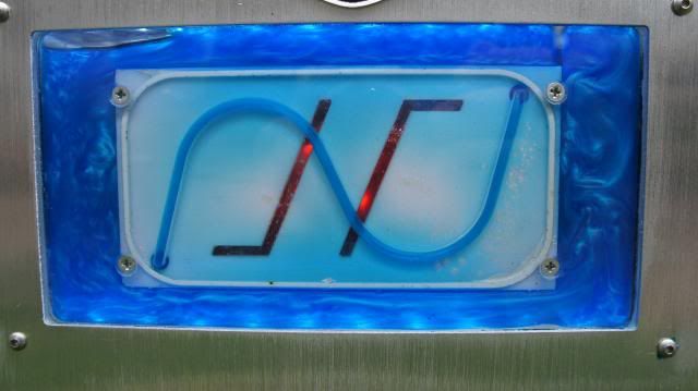
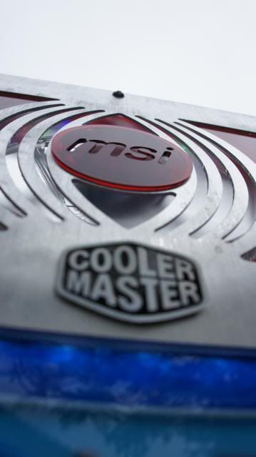
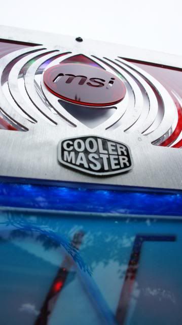
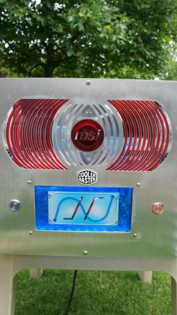
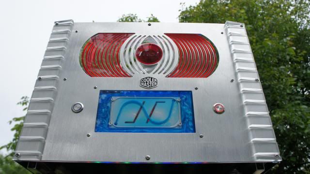
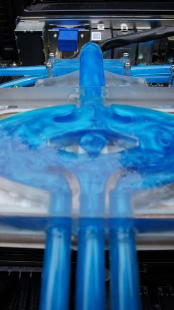
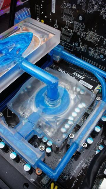
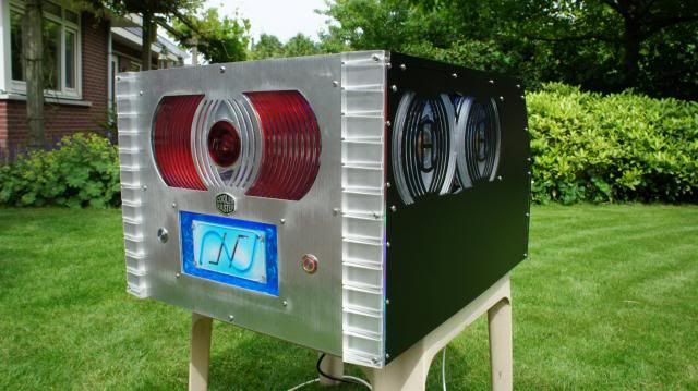
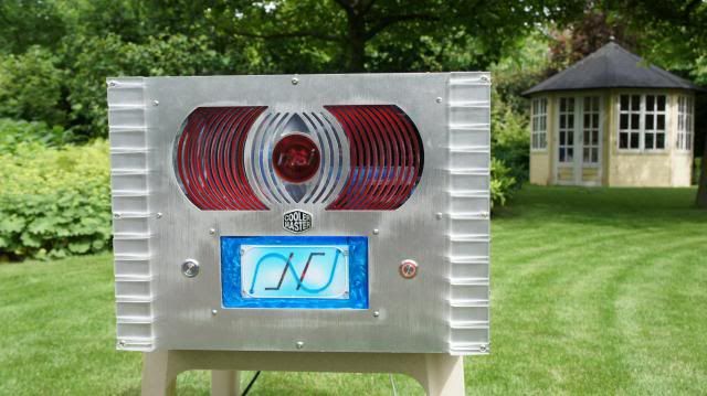
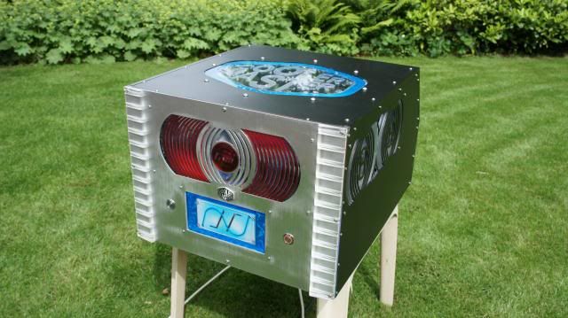
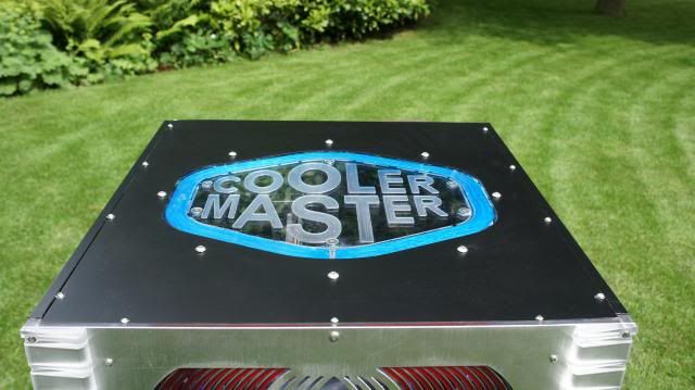
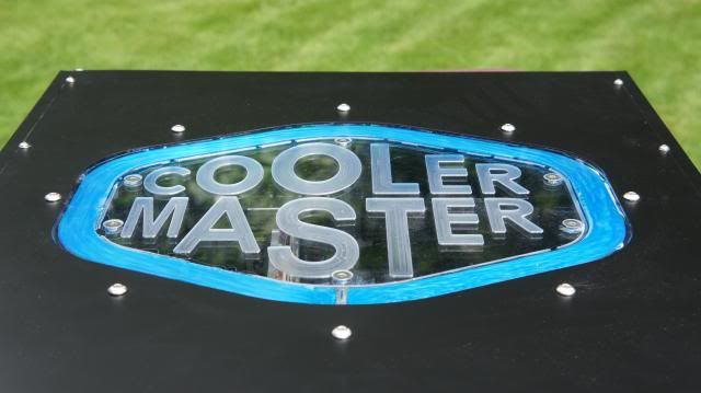
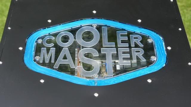
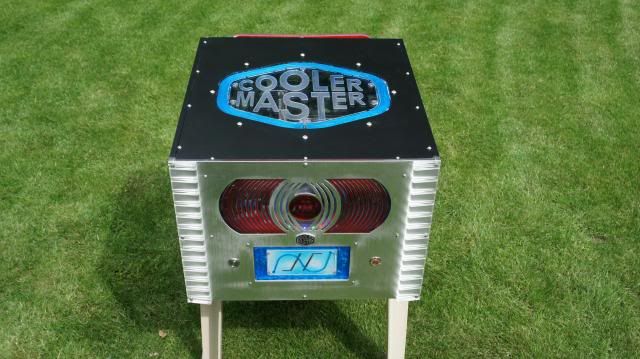
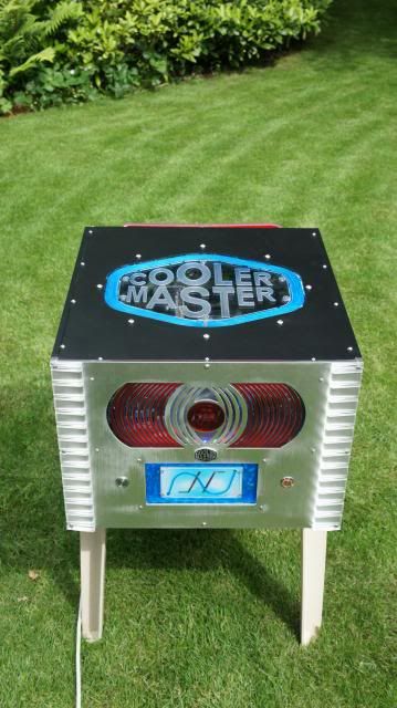
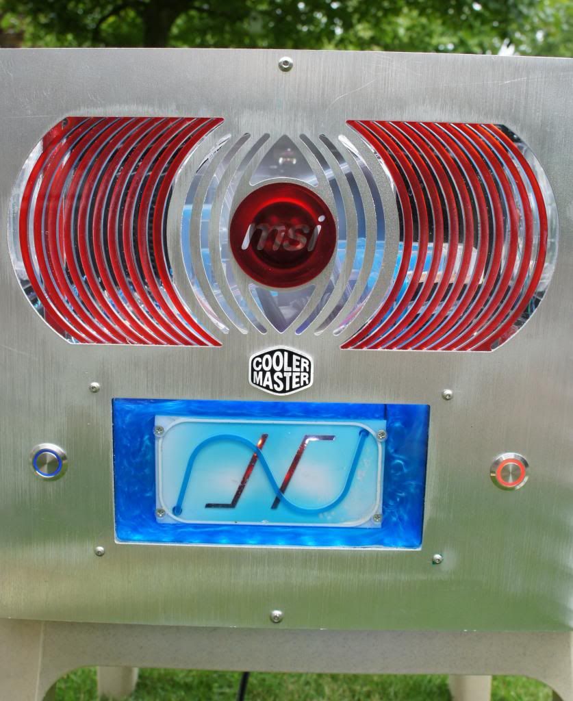
hello everybody, if your reading this it means my build is already complete  because of the rules of the contest where this case was made for I could not post any pictures before the end of the contest.
unfortunataly my german is not as good as it was so that is why it is in english.
so prepare yourself for some 250+ pictures of the build I made :P
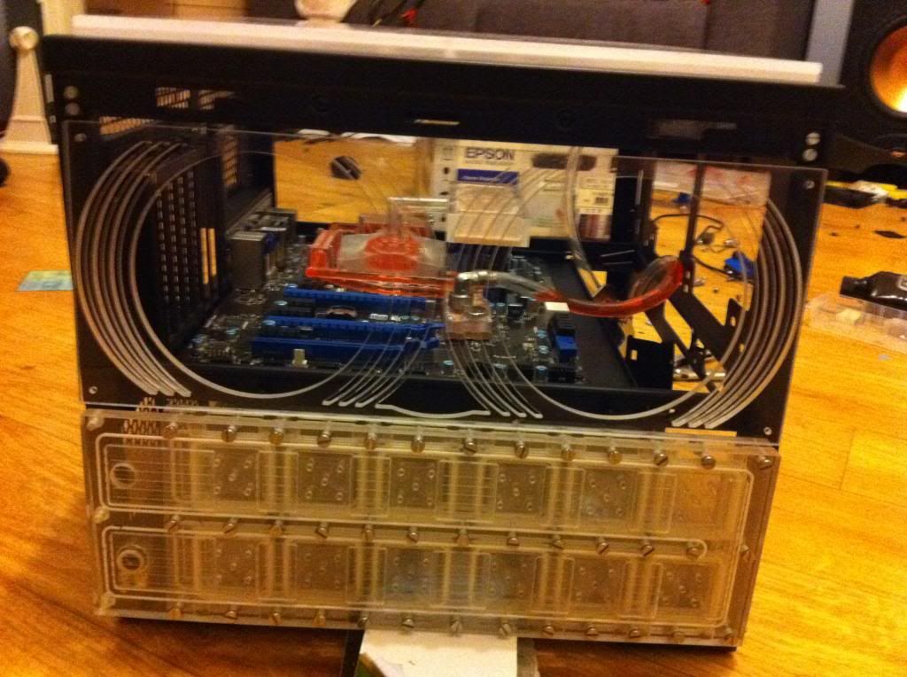
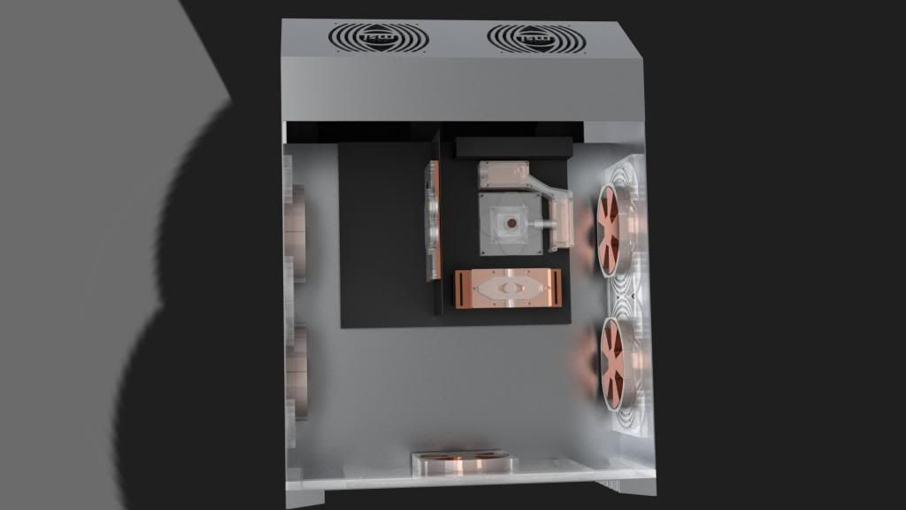
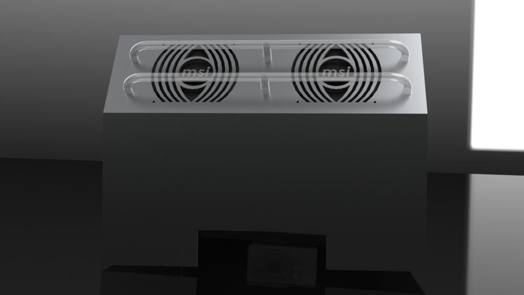
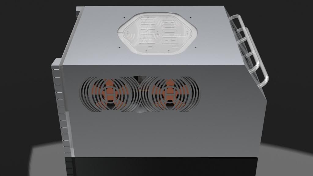
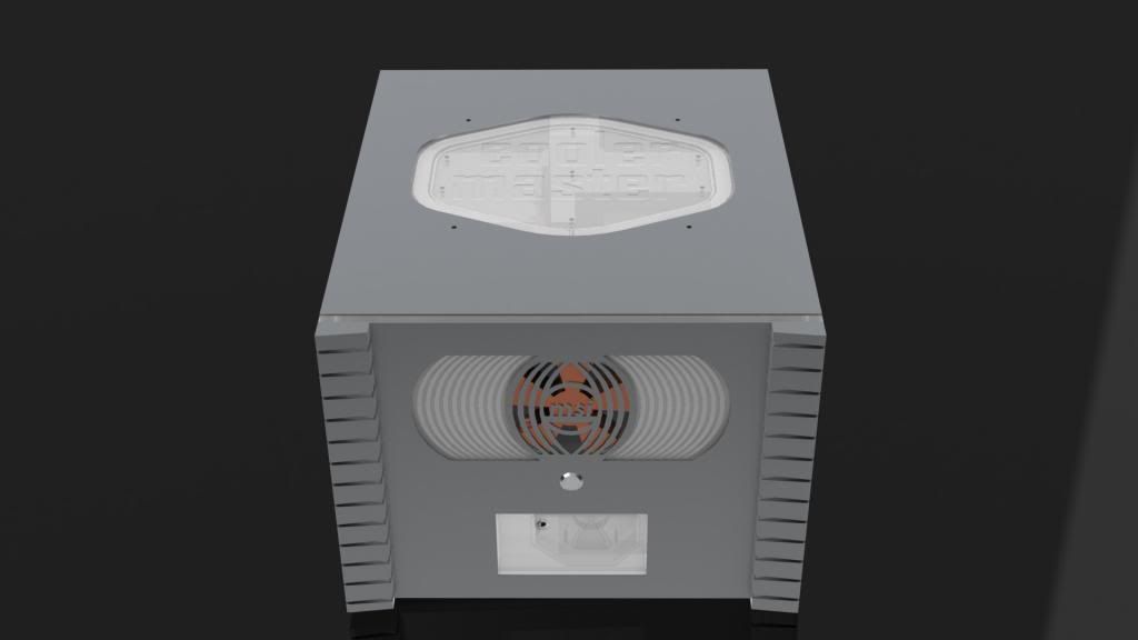
before I begin I want to show you the renders of the case, these were made with solidworks and therefore the coolant is not there like most people use in sketchup:
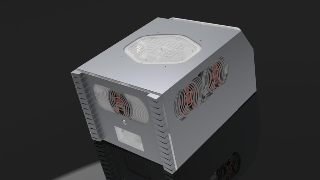
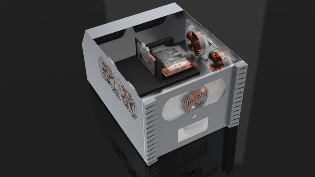
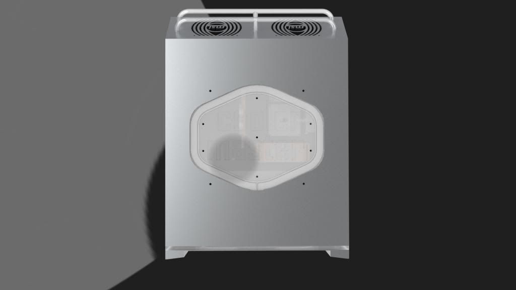
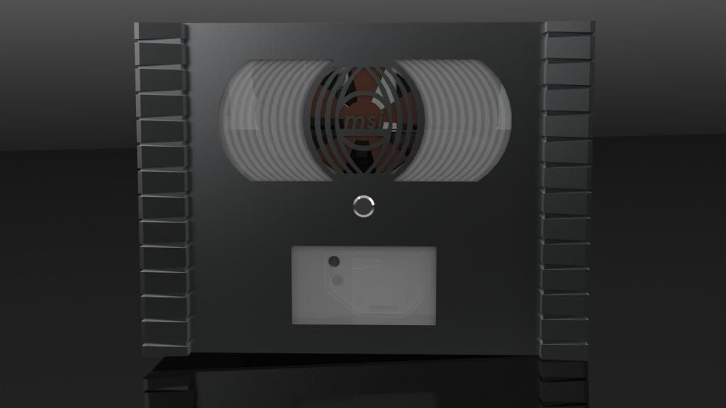
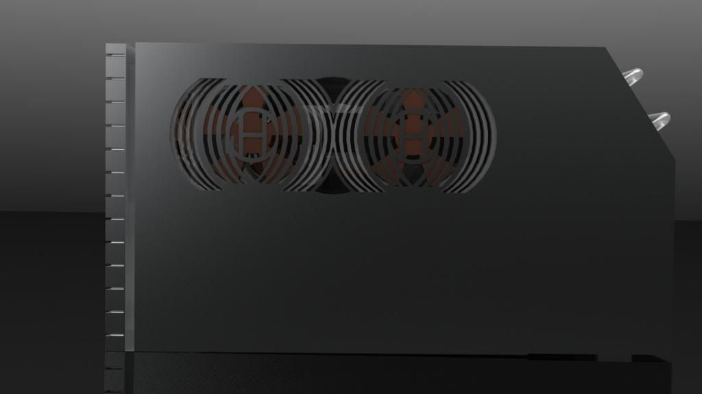
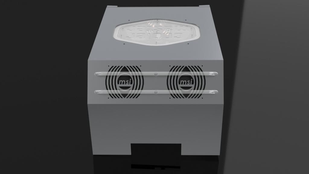
also a chiller was made but it had a separate build log so I'm not going to post that again. you can find it with Dutch description here: super cool
just use Google translate :P the rest of the build will be here
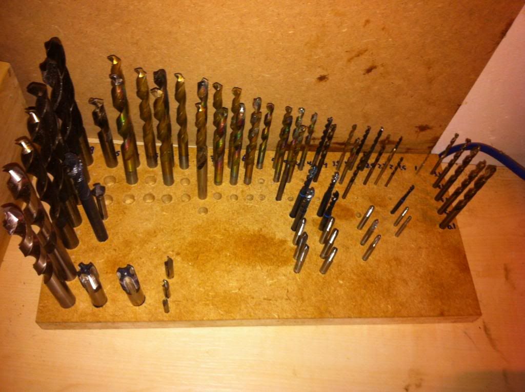
first of I want to start by showing everybody the tools I used during this build:
my drills:
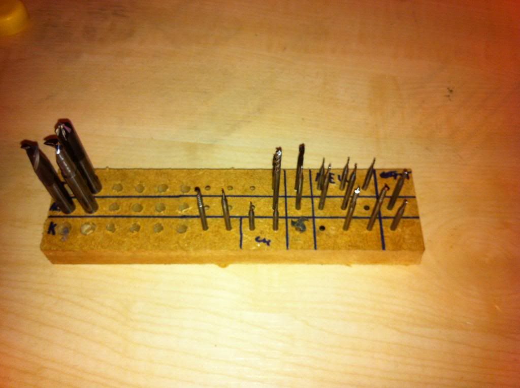
my end mills:
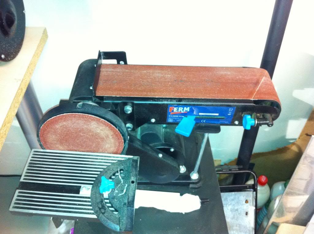
the belt an disk sander:
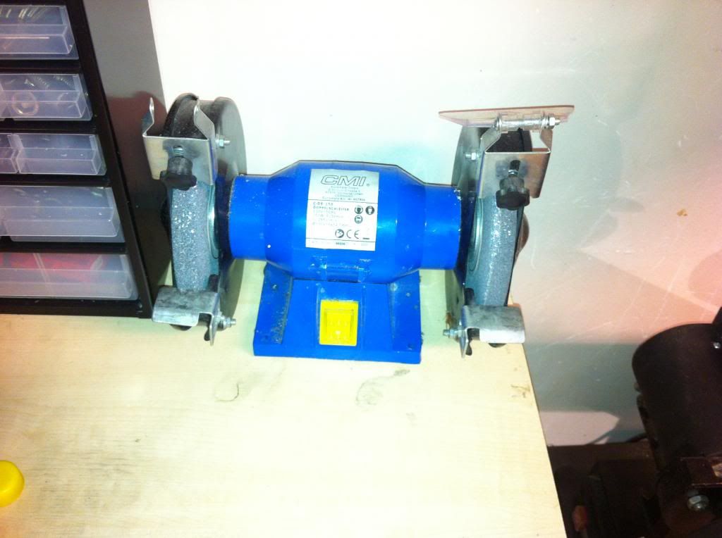
my el cheapo disk grinder:
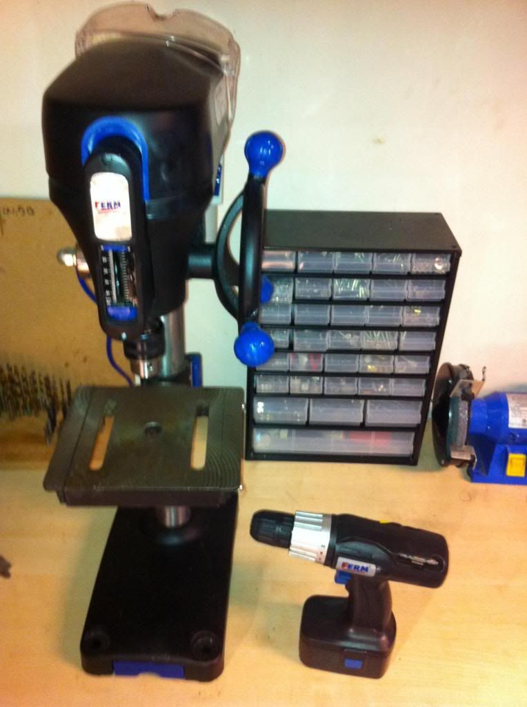
ferm drill press:
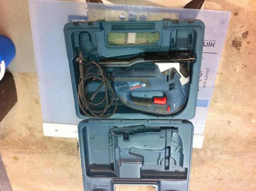
bosch blue jigsaw:
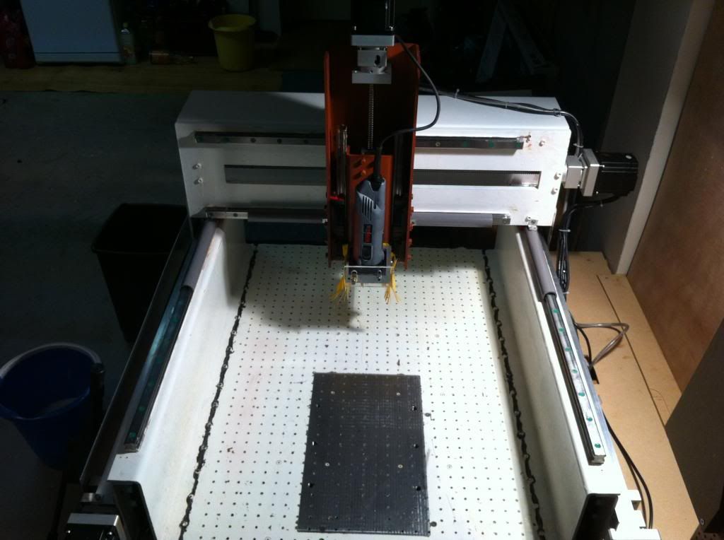
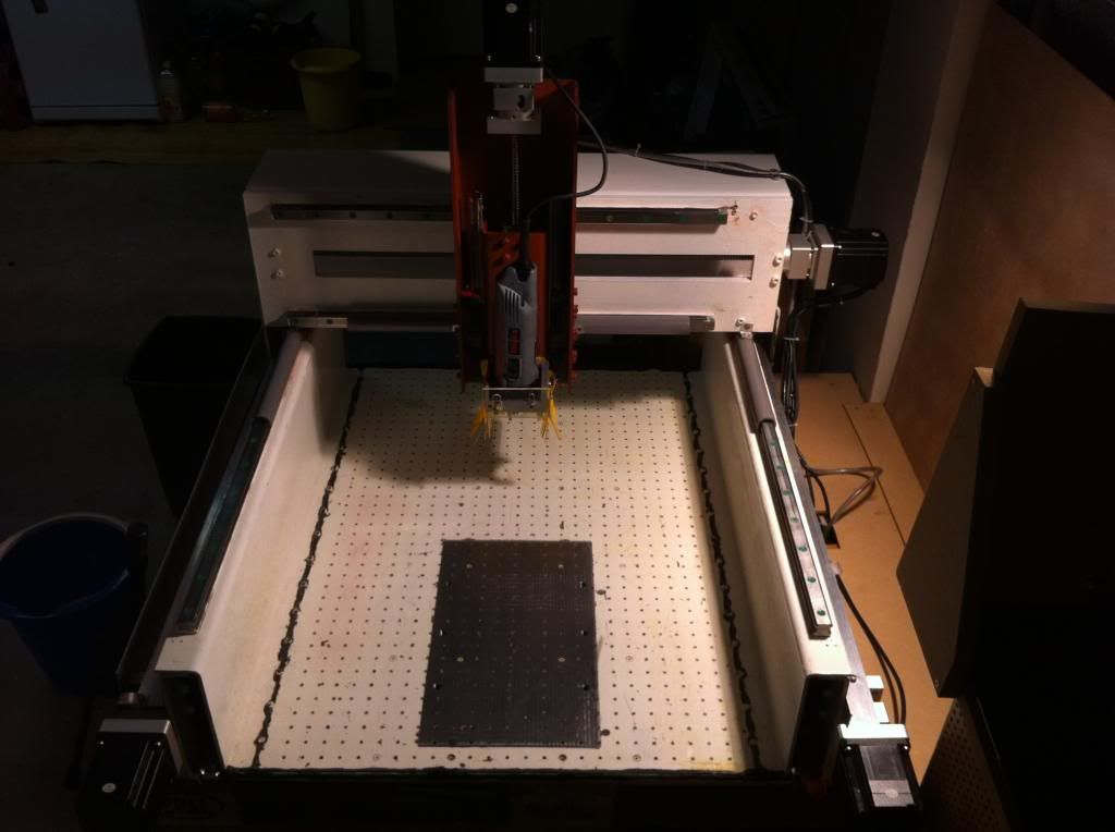
my self designed and build cnc machine(700mmx550mm range)
---------- Post added at 15:03 ---------- Previous post was at 15:02 ----------
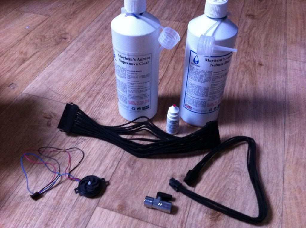
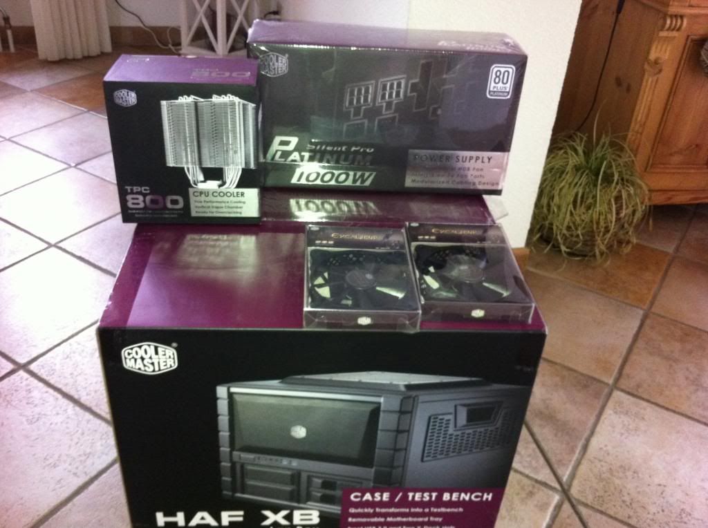
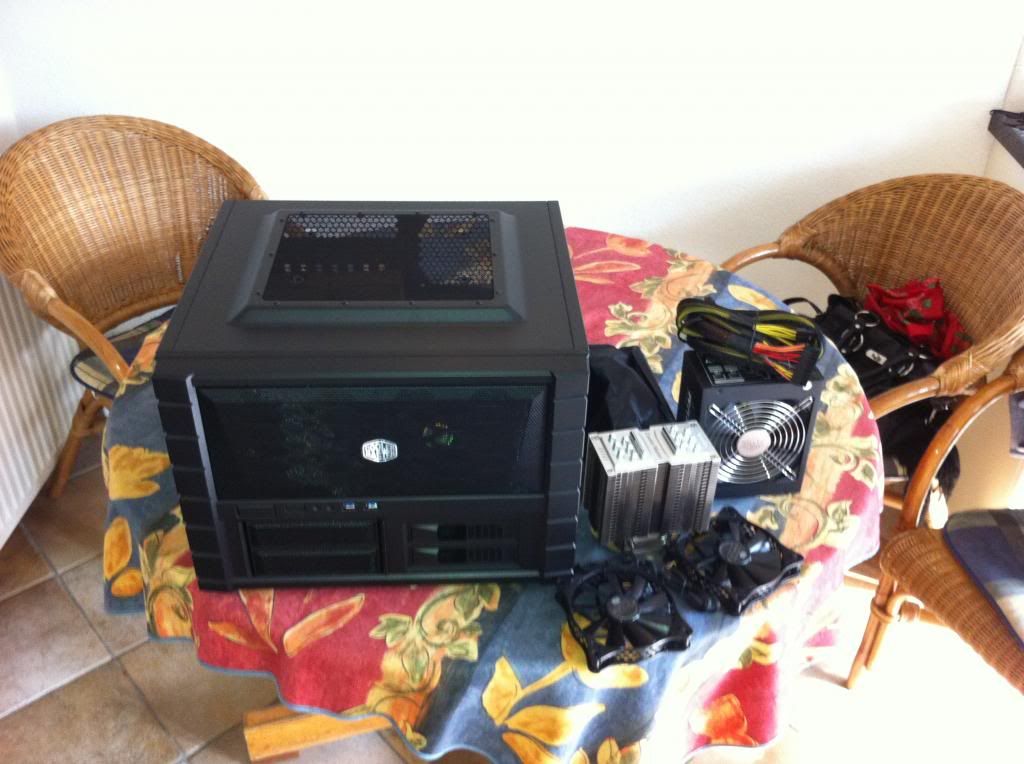
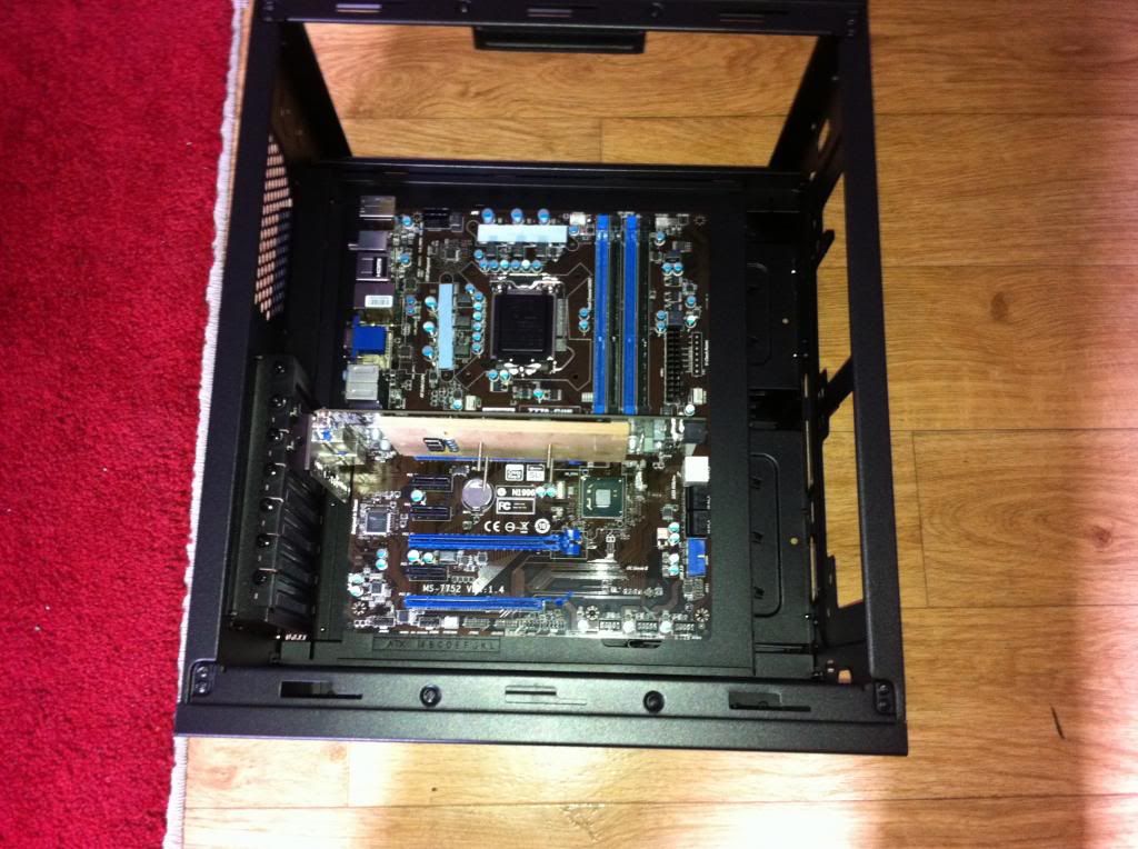
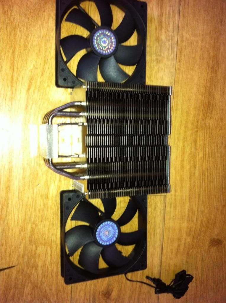
update 1 goodies arrive:
I think this is rather self explanatory.
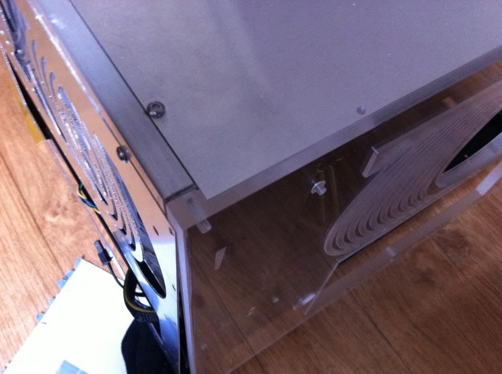
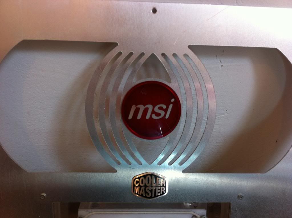
first the msi stuff:
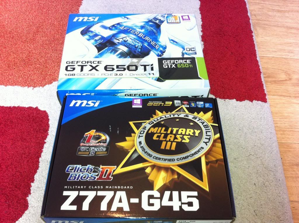
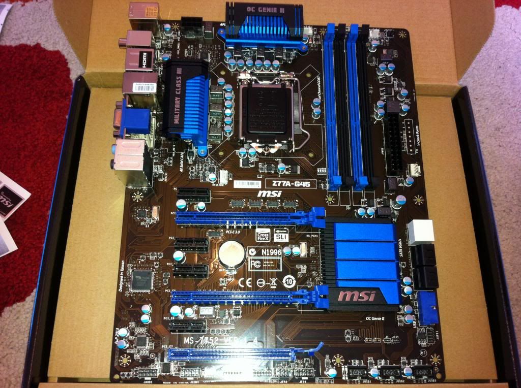
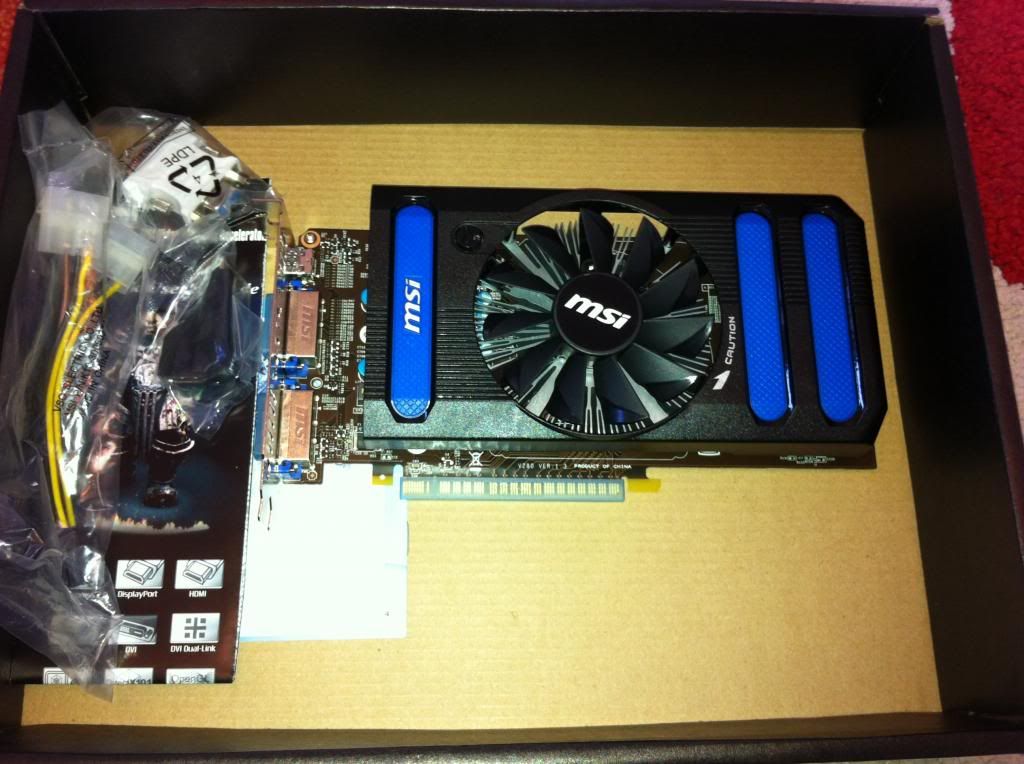
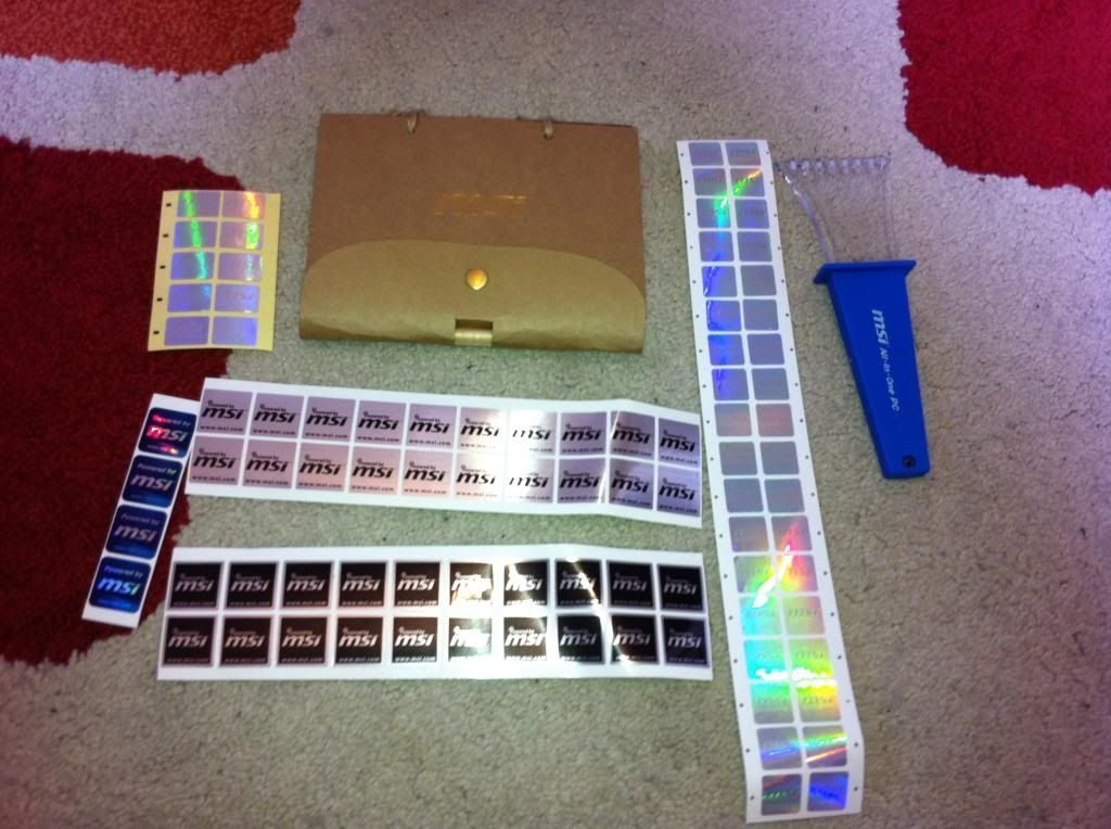
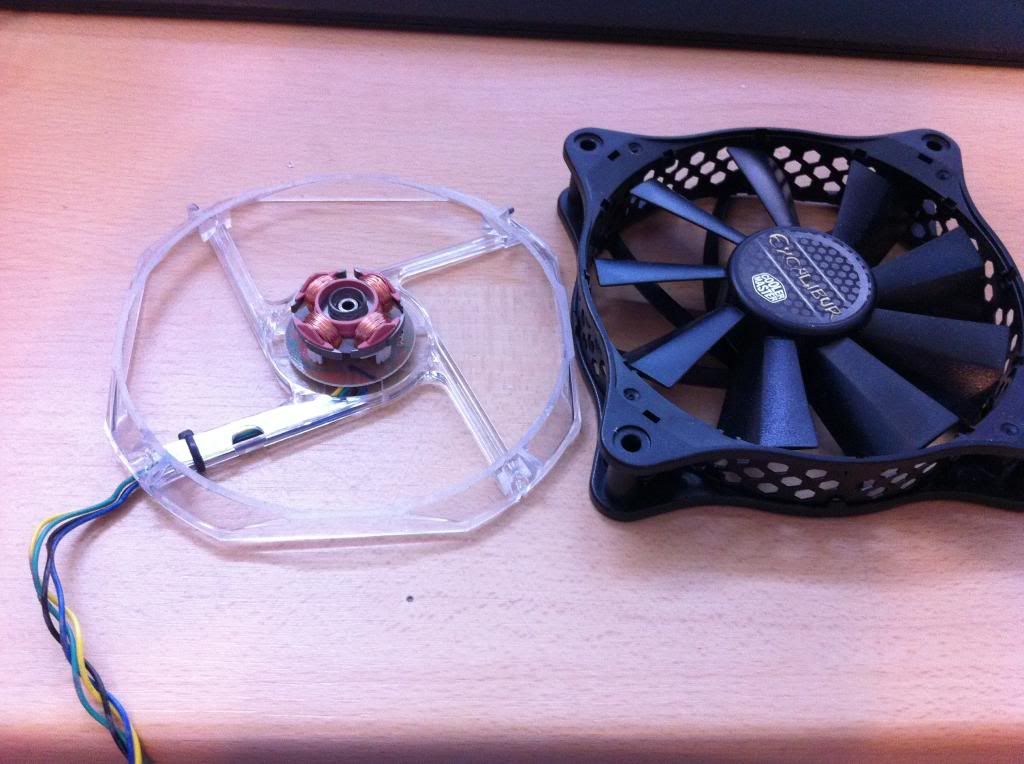
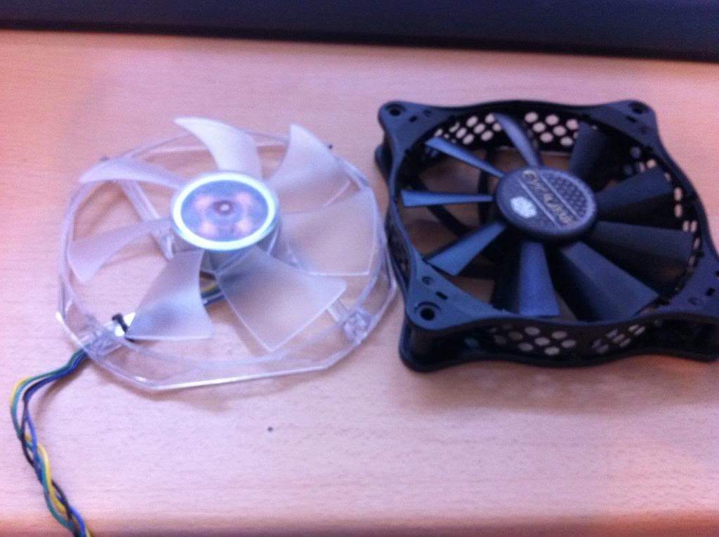
and the cooler master parts:
---------- Post added at 15:03 ---------- Previous post was at 15:03 ----------
update 1 goodies arrive:
I think this is rather self explanatory.
first the msi stuff:


and the cooler master parts:


---------- Post added at 15:05 ---------- Previous post was at 15:03 ----------
update 2 mdf gpu prototype and first plexi window
I already had some sketchup file of the graphics card so with a little adjustment I started the work for the full cover gpu block. of course first starting with a cheap material like mdf for prototype:
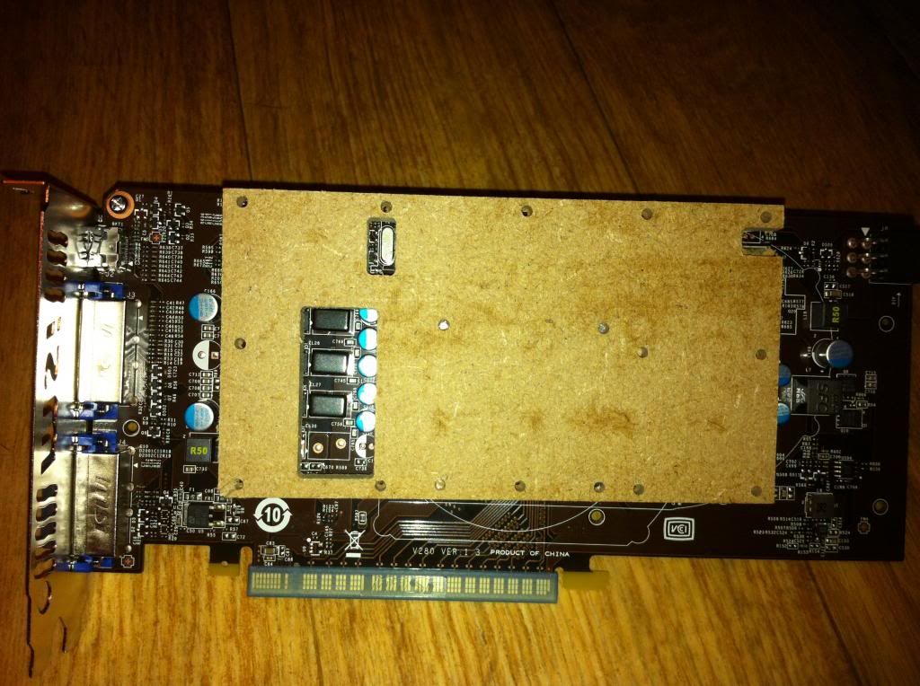
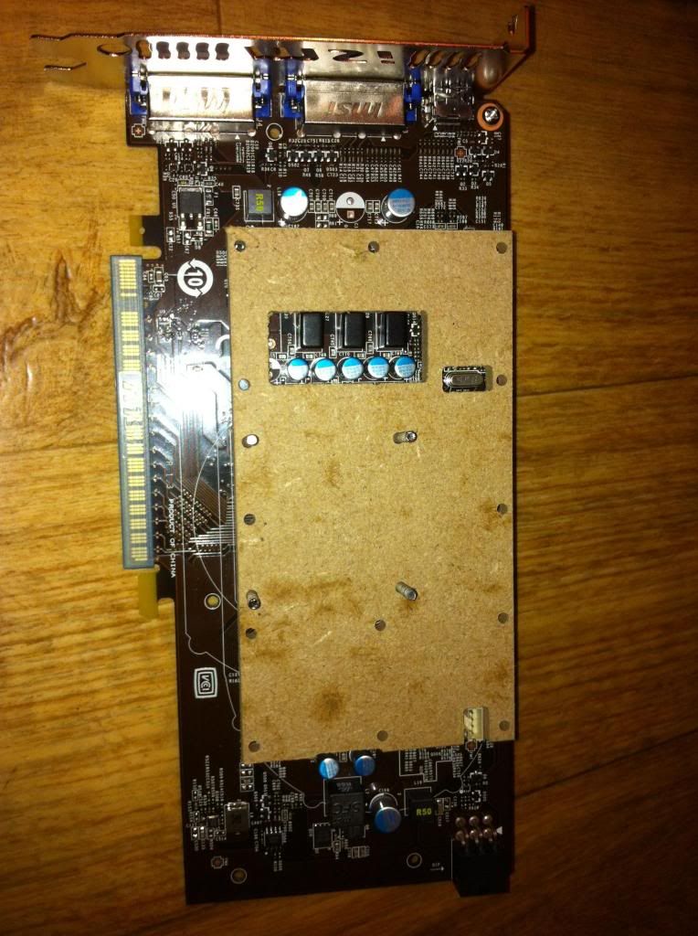
it took about 3 tries before I got it right, luckily it took only 2 mins of time to make a prototype
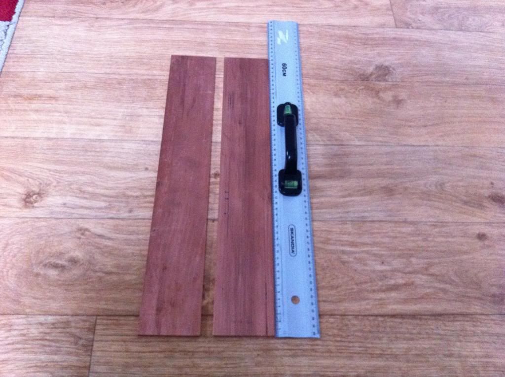
that day also the copper arrived(80*500*5mm bars)
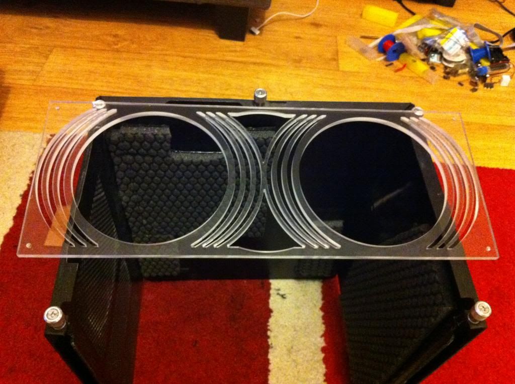
I also made the first of 2 side windows:
update 3 the top window
I started making the top window but unfortunately it was not good enough by my standards so later on I will be redoing it, but it shows the evolving process so no harm showing it:
first prepared with a 1,5mm 1flute end mill:
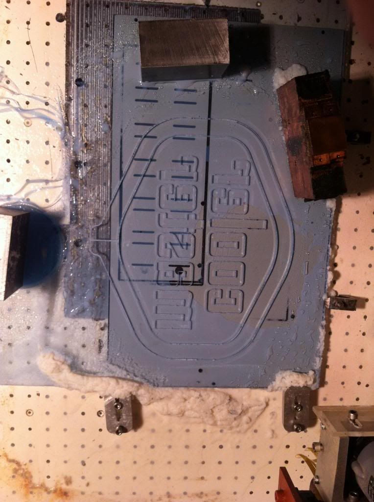
next with a 3mm end mill to make the waterway and the inside of the letters:
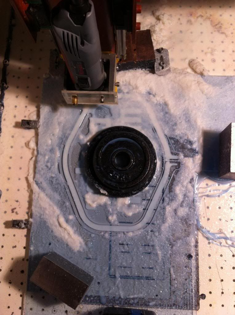
next couple are the result:
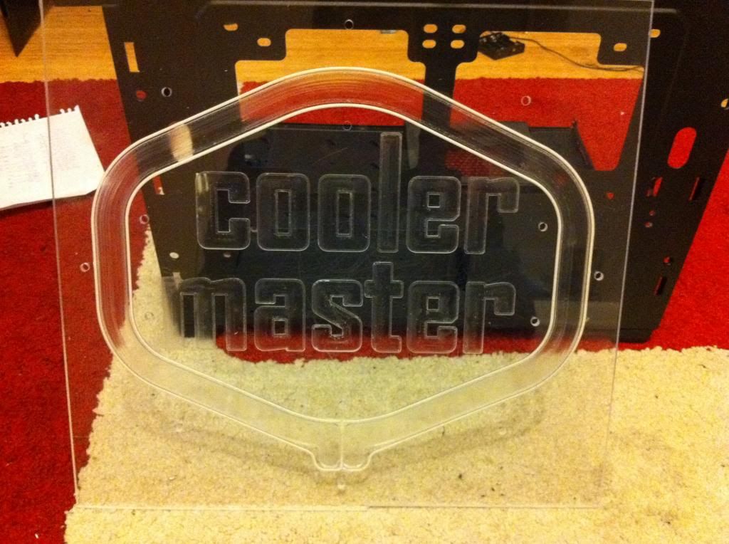
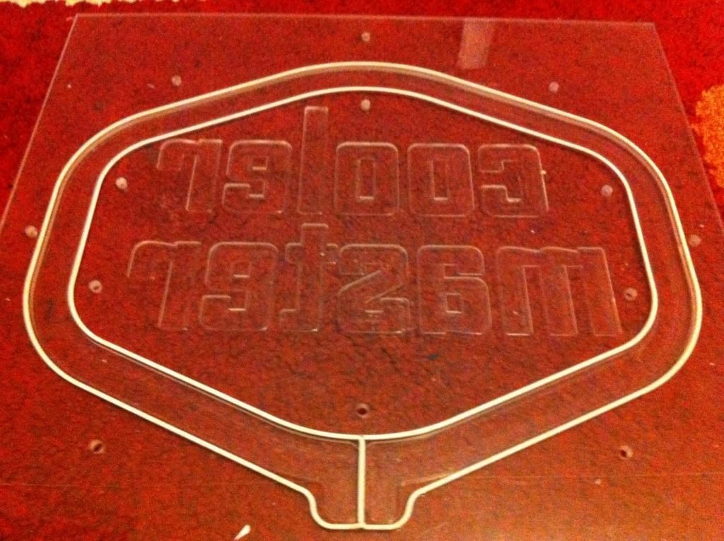
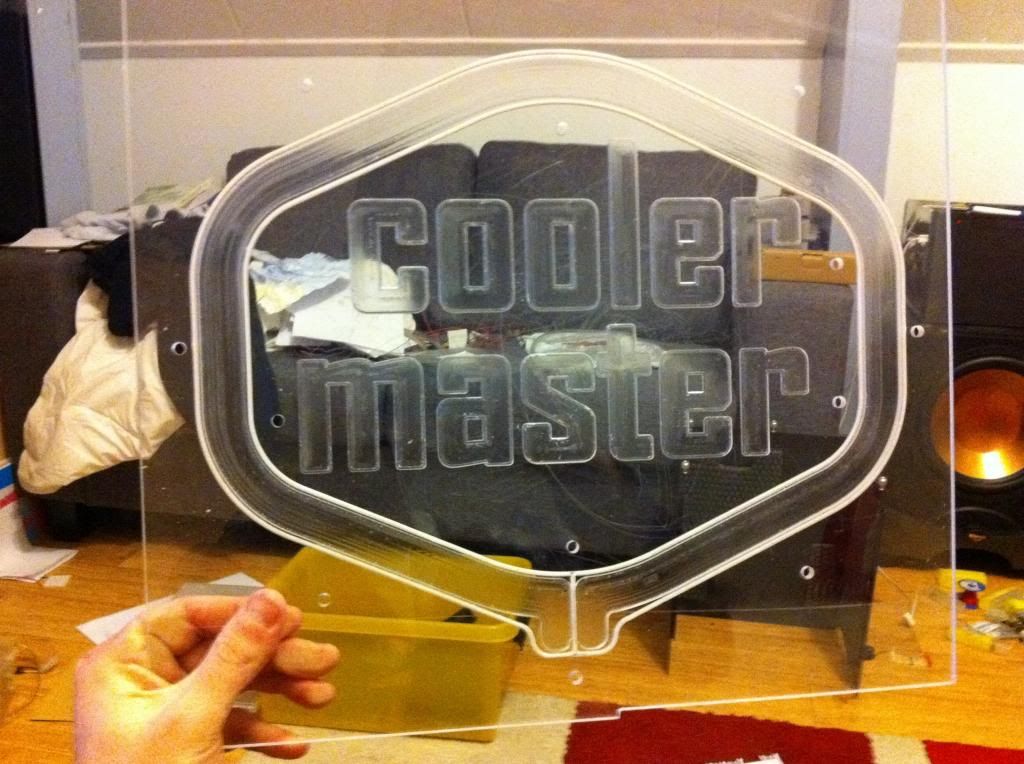
the last one shows why I didn't use it, too many scratches and the letters are awful :P
---------- Post added at 15:05 ---------- Previous post was at 15:05 ----------
update 2 mdf gpu prototype and first plexi window
I already had some sketchup file of the graphics card so with a little adjustment I started the work for the full cover gpu block. of course first starting with a cheap material like mdf for prototype:


it took about 3 tries before I got it right, luckily it took only 2 mins of time to make a prototype
that day also the copper arrived(80*500*5mm bars)

I also made the first of 2 side windows:

update 3 the top window
I started making the top window but unfortunately it was not good enough by my standards so later on I will be redoing it, but it shows the evolving process so no harm showing it:
first prepared with a 1,5mm 1flute end mill:

next with a 3mm end mill to make the waterway and the inside of the letters:

next couple are the result:


the last one shows why I didn't use it, too many scratches and the letters are awful :P
---------- Post added at 15:06 ---------- Previous post was at 15:05 ----------
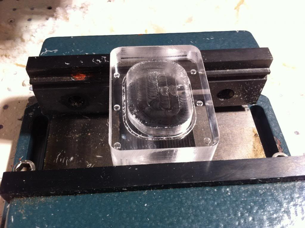
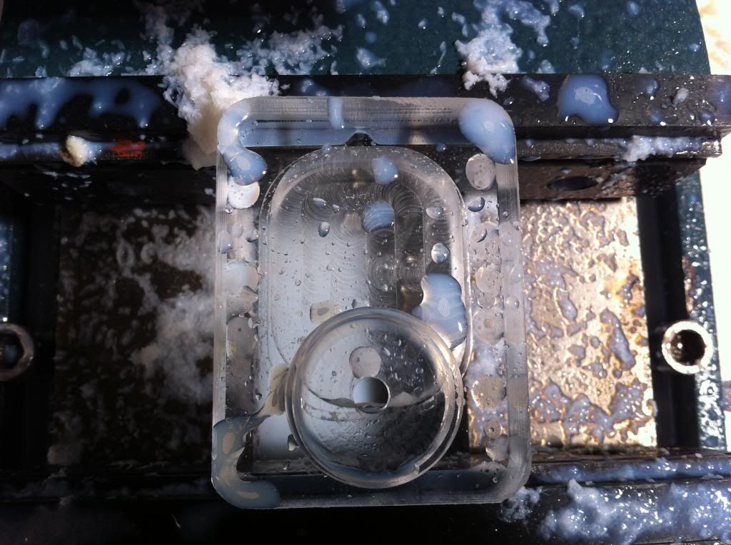
update 4 start of the reservoir:
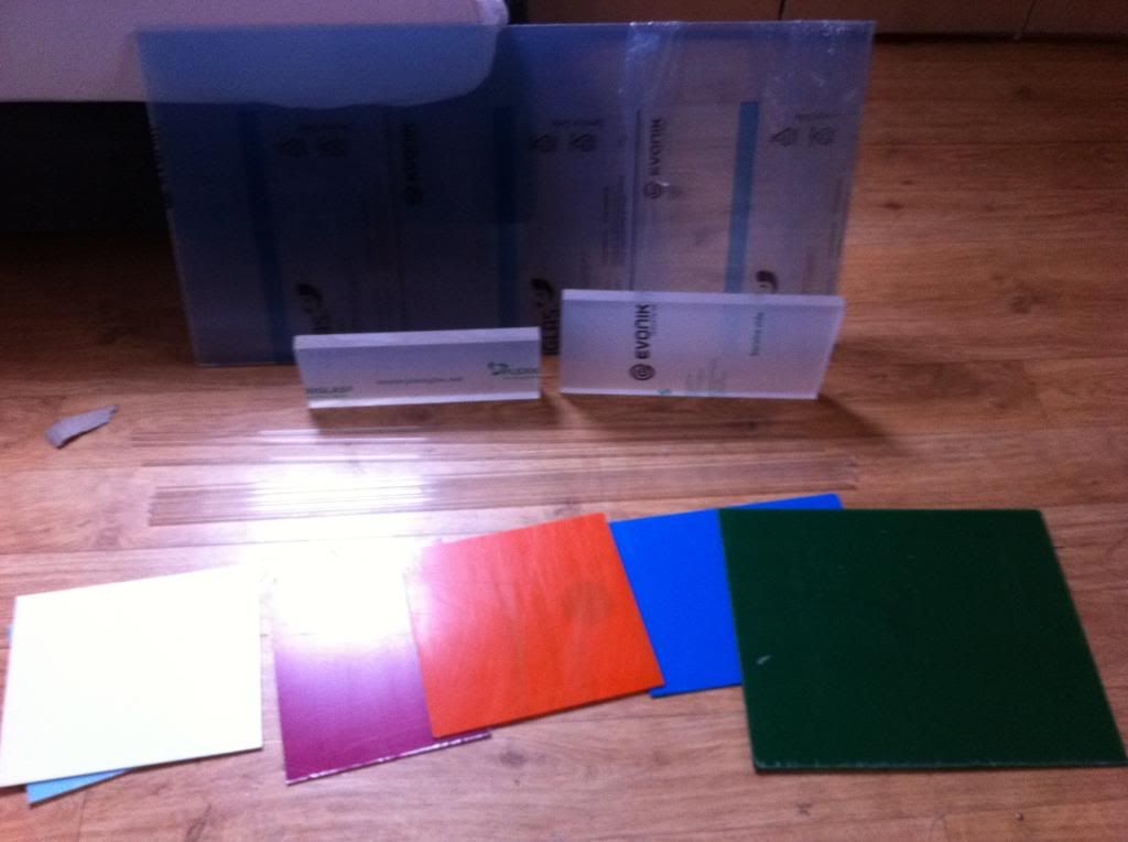
first I will show you the materials I got that day:
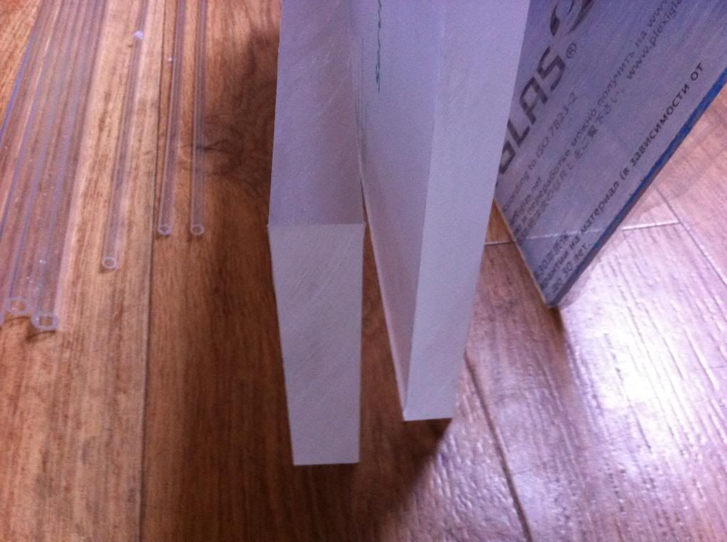
the biggest piece is 5mm 100x50cm next biggest is 20mm thick and will be used for the cpu cooler, ram cooler, mosfet cooler and the Southbridge cooler. the last piece will be used for the reservoir's(there are 2)
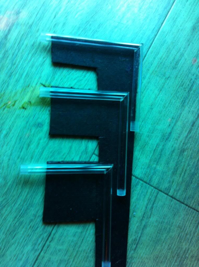
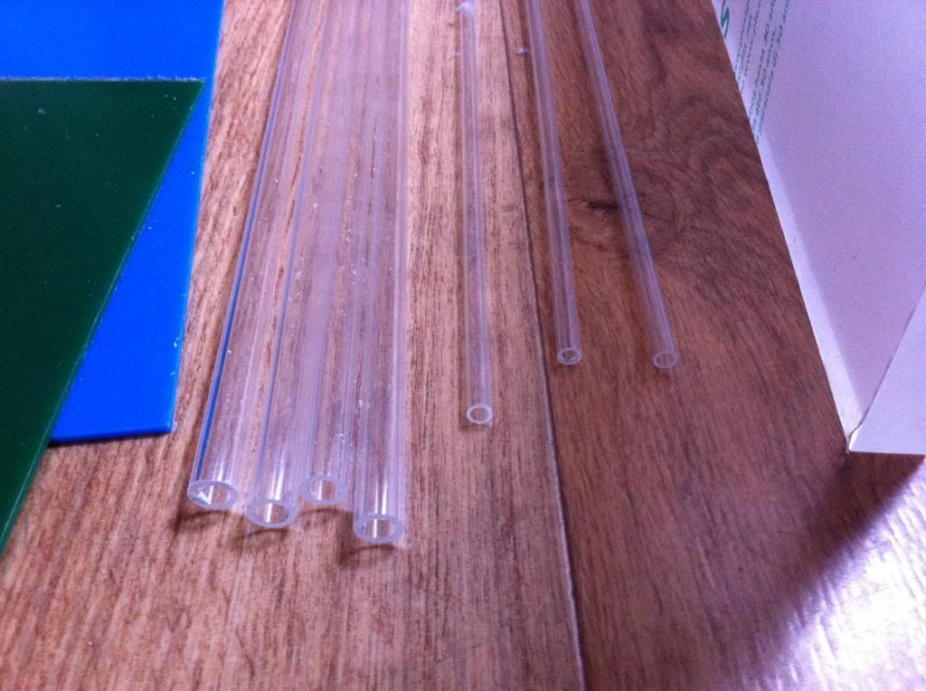
also some acrylic pipes(12mm and 7mm)
in the evening I started milling the reservoir, first part was done with a 8mm 1f end mill:
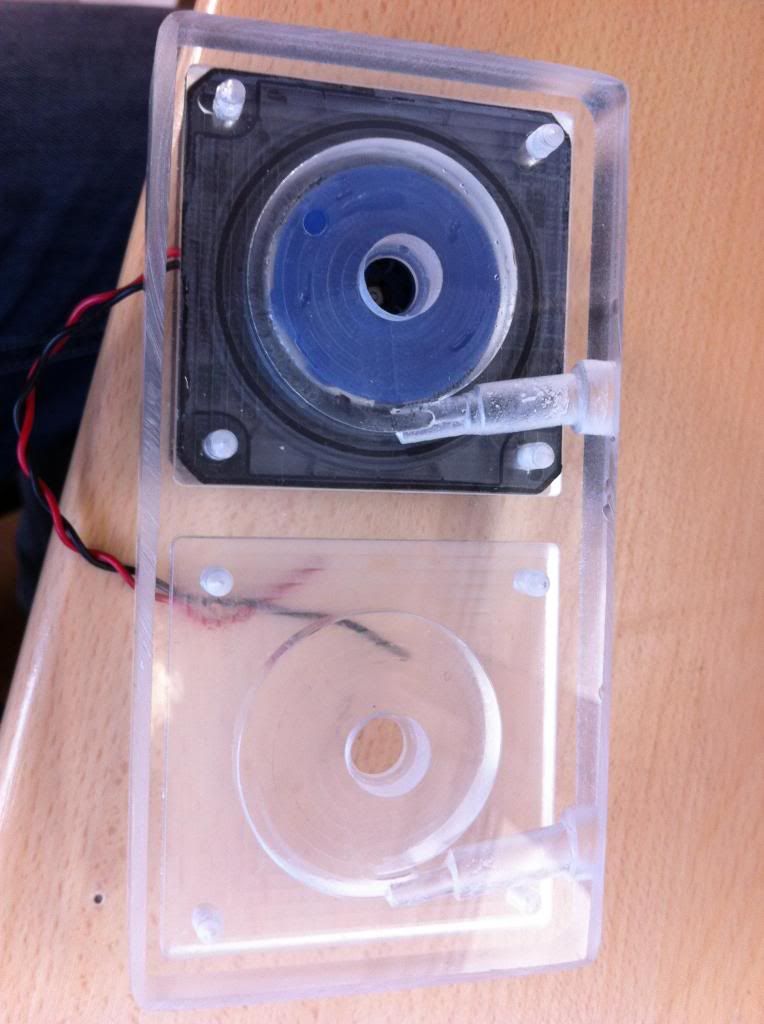
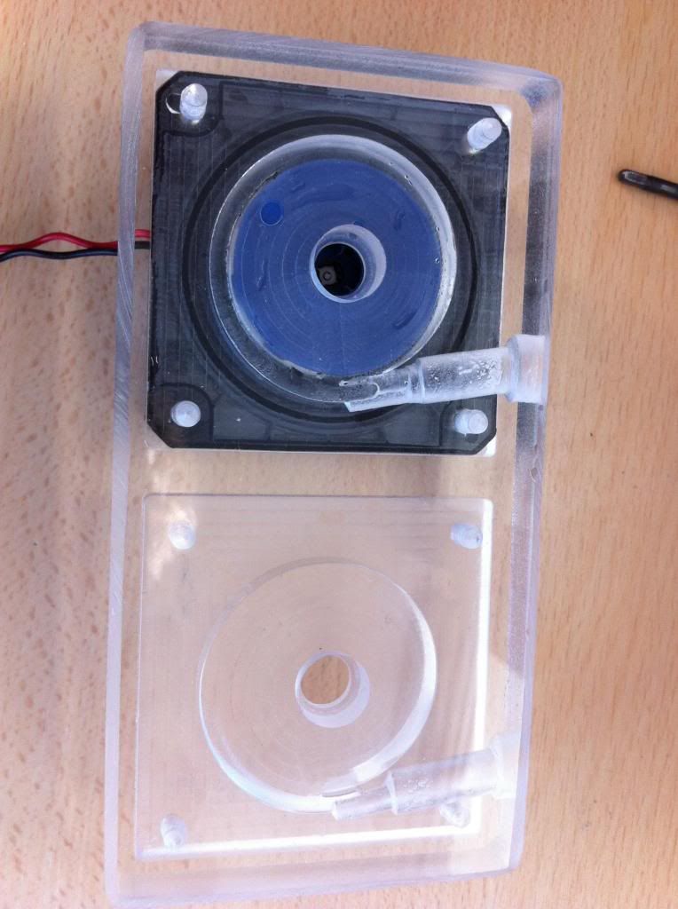
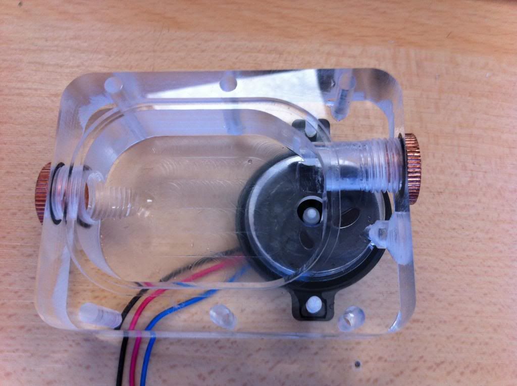
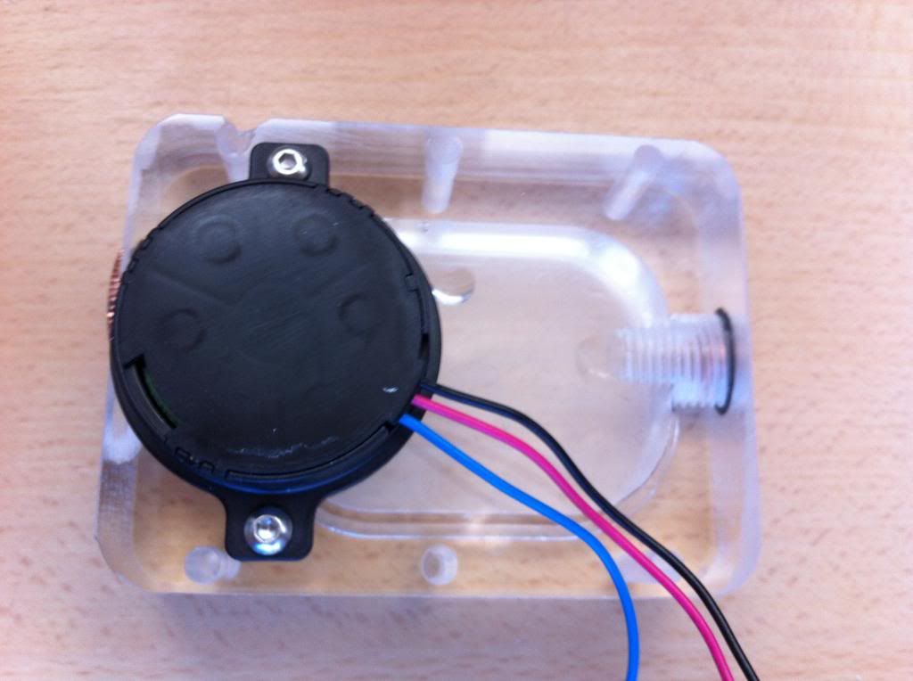
it is going to be a 2 part reservoir that is combined into one.
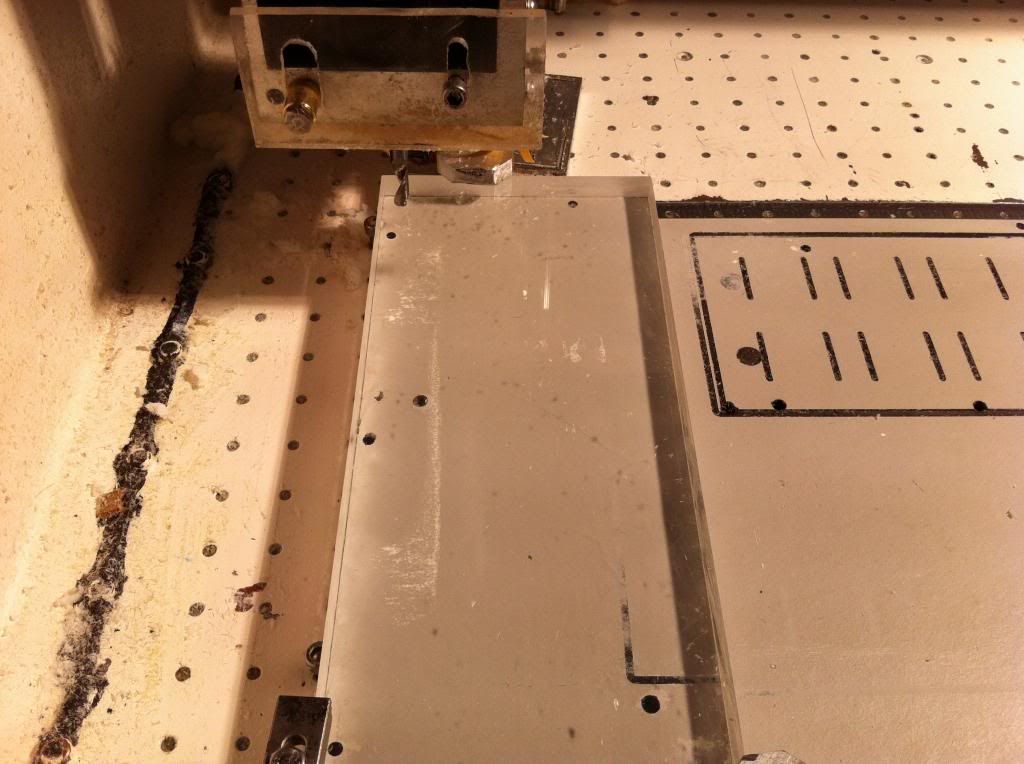
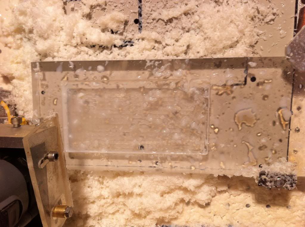
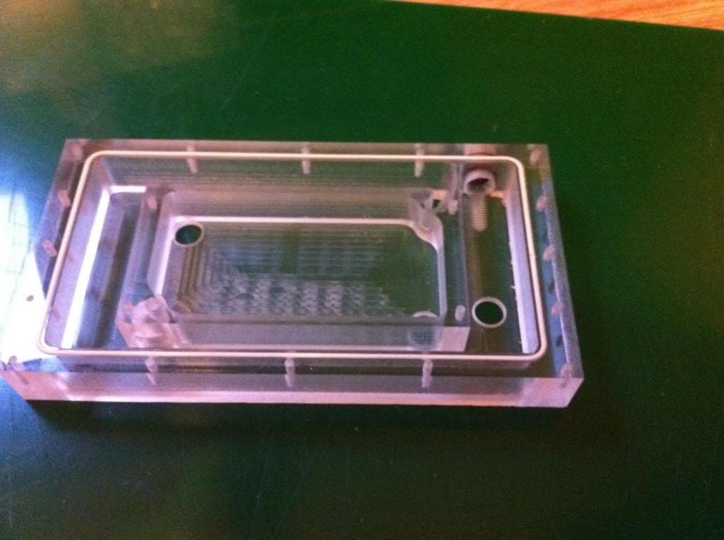
the finished first piece:
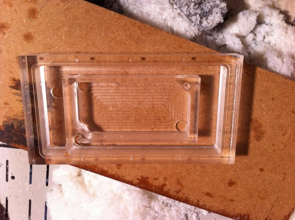
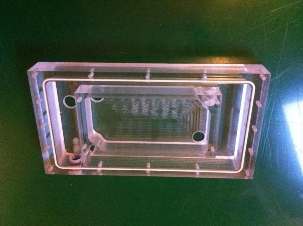
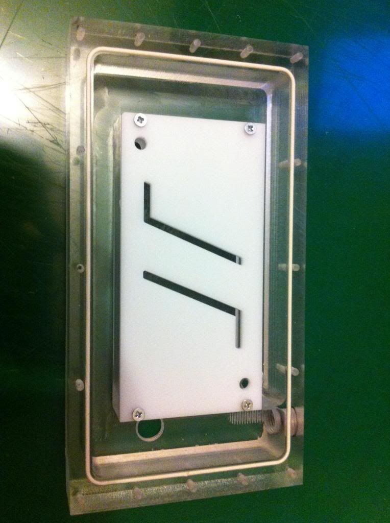
next I made the white acrylic top plate for the middle reservoir:
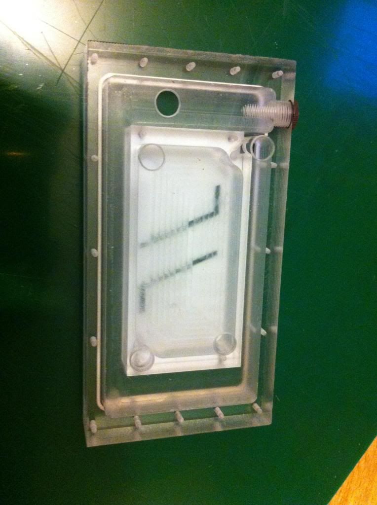
finally I made the top plate of the outside reservoir:
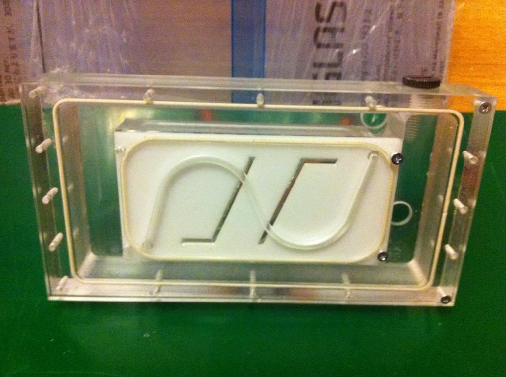
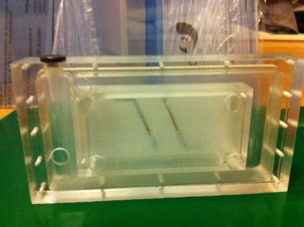
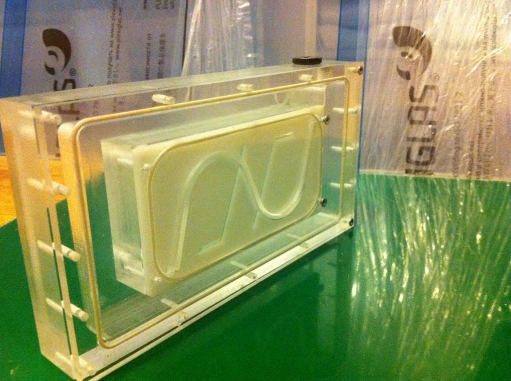
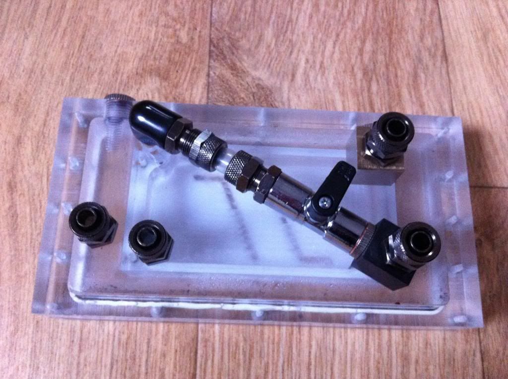
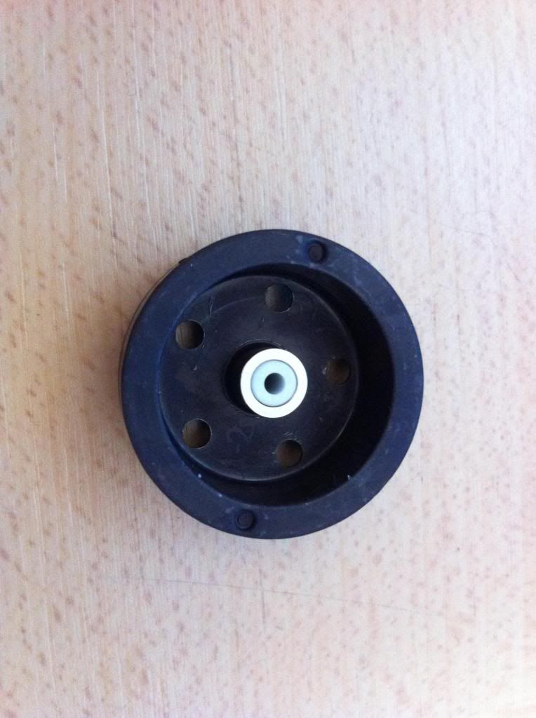
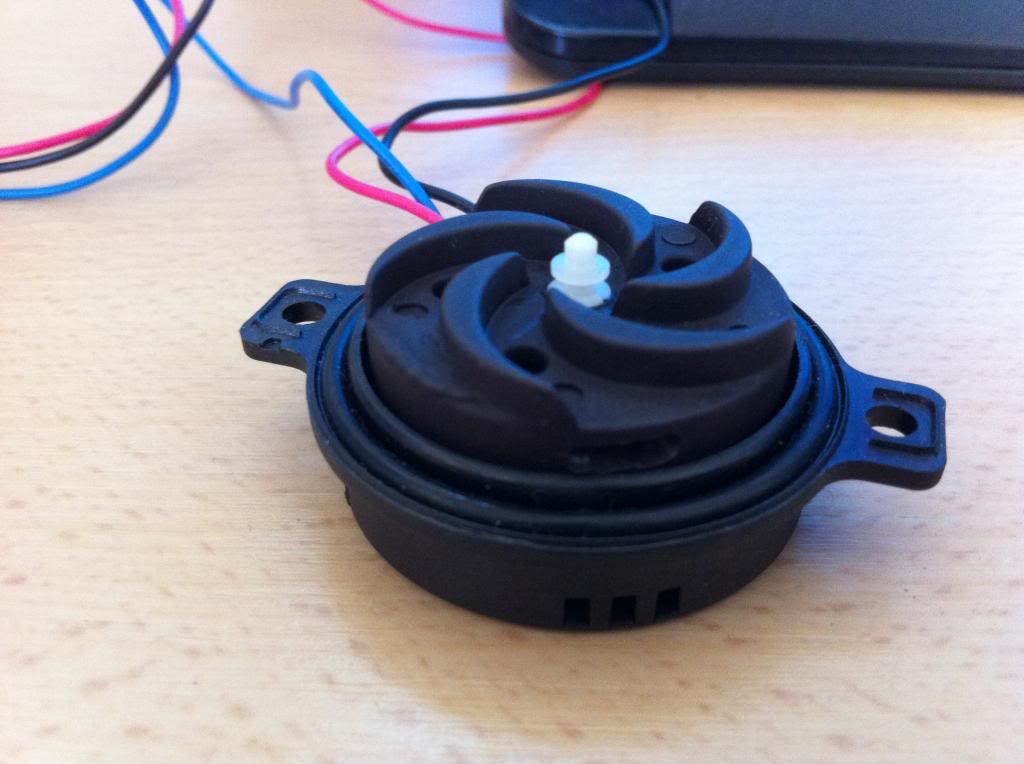
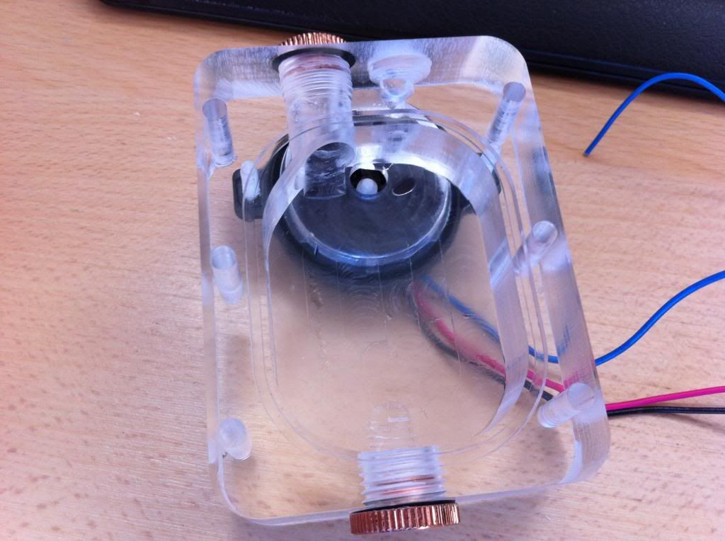
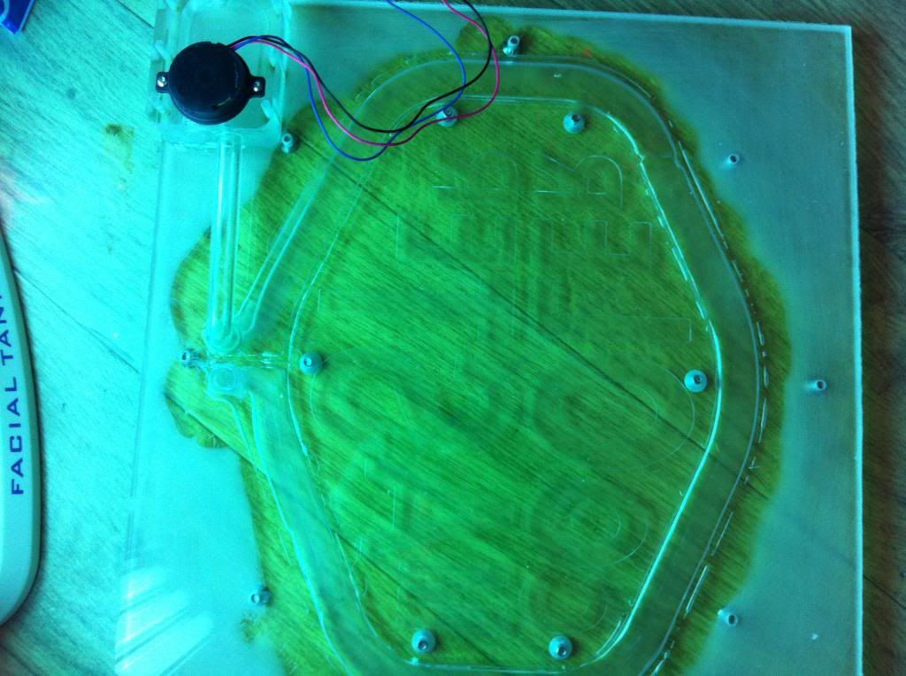
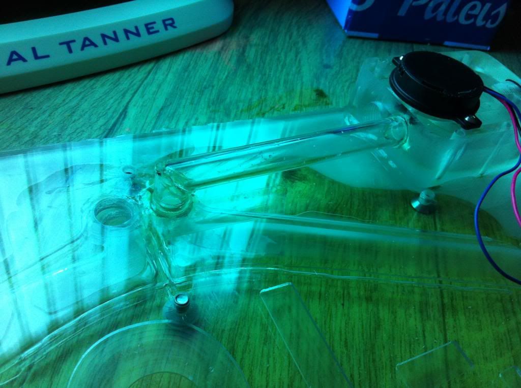
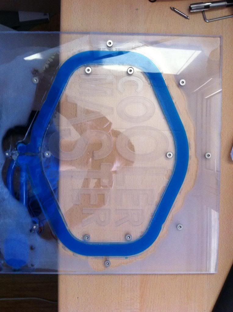
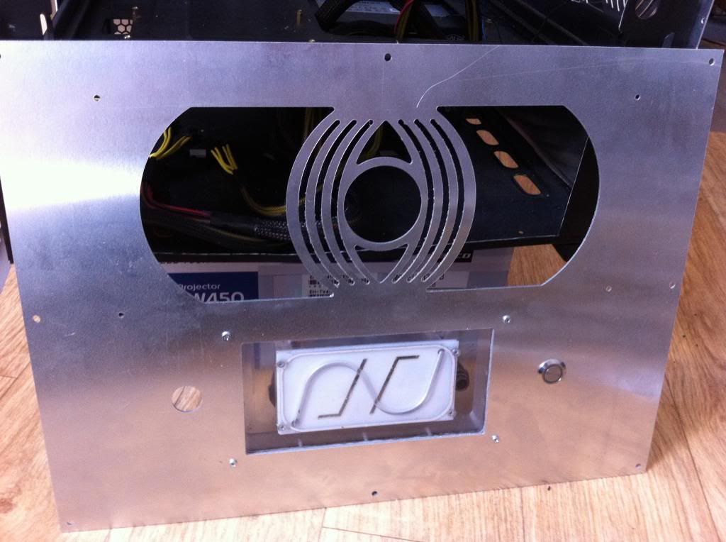
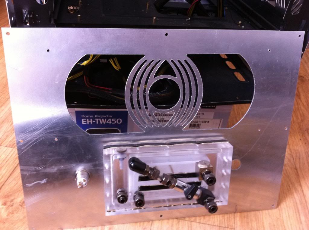
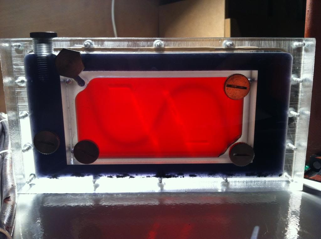
as you can see there are 5 inlets/outlets on the reservoir, this is done because the water can go in front of the middle reservoir via the sling, but this can be very restrictive so I made a parallel line with a valve to be able to regulate the flow.
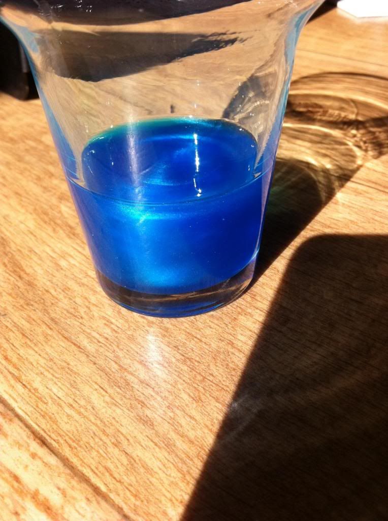
here are some pictures of the res with some fluid inside(this is not the final fluid)
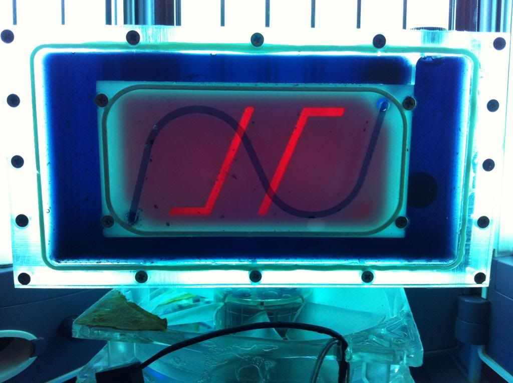
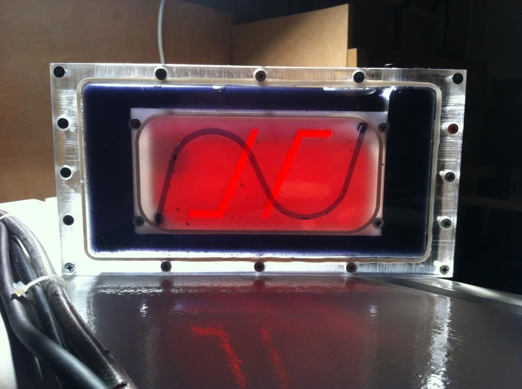
---------- Post added at 15:06 ---------- Previous post was at 15:06 ----------
update 4 start of the reservoir:
first I will show you the materials I got that day:
the biggest piece is 5mm 100x50cm next biggest is 20mm thick and will be used for the cpu cooler, ram cooler, mosfet cooler and the Southbridge cooler. the last piece will be used for the reservoir's(there are 2)

also some acrylic pipes(12mm and 7mm)


in the evening I started milling the reservoir, first part was done with a 8mm 1f end mill:
it is going to be a 2 part reservoir that is combined into one.


the finished first piece:


next I made the white acrylic top plate for the middle reservoir:


finally I made the top plate of the outside reservoir:


as you can see there are 5 inlets/outlets on the reservoir, this is done because the water can go in front of the middle reservoir via the sling, but this can be very restrictive so I made a parallel line with a valve to be able to regulate the flow.
here are some pictures of the res with some fluid inside(this is not the final fluid)


---------- Post added at 15:07 ---------- Previous post was at 15:06 ----------
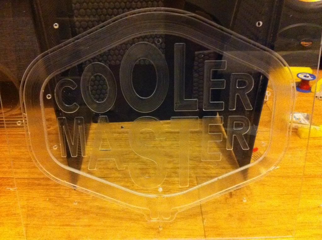
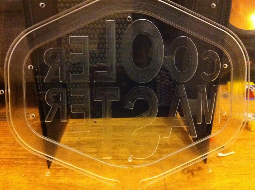
update 5 new top window:
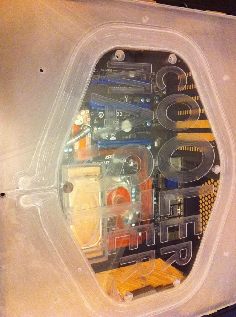
as I said before the top window was not up to my standards so I redid it with better letters and this time no scratches:
update 6 cpu cooler:
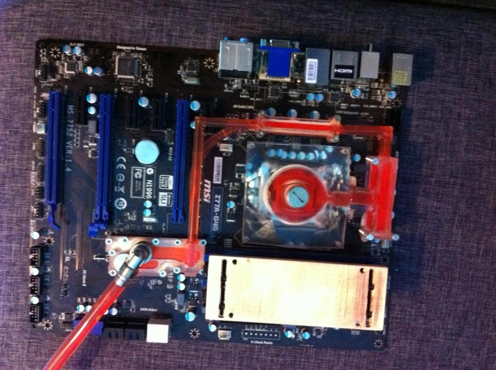
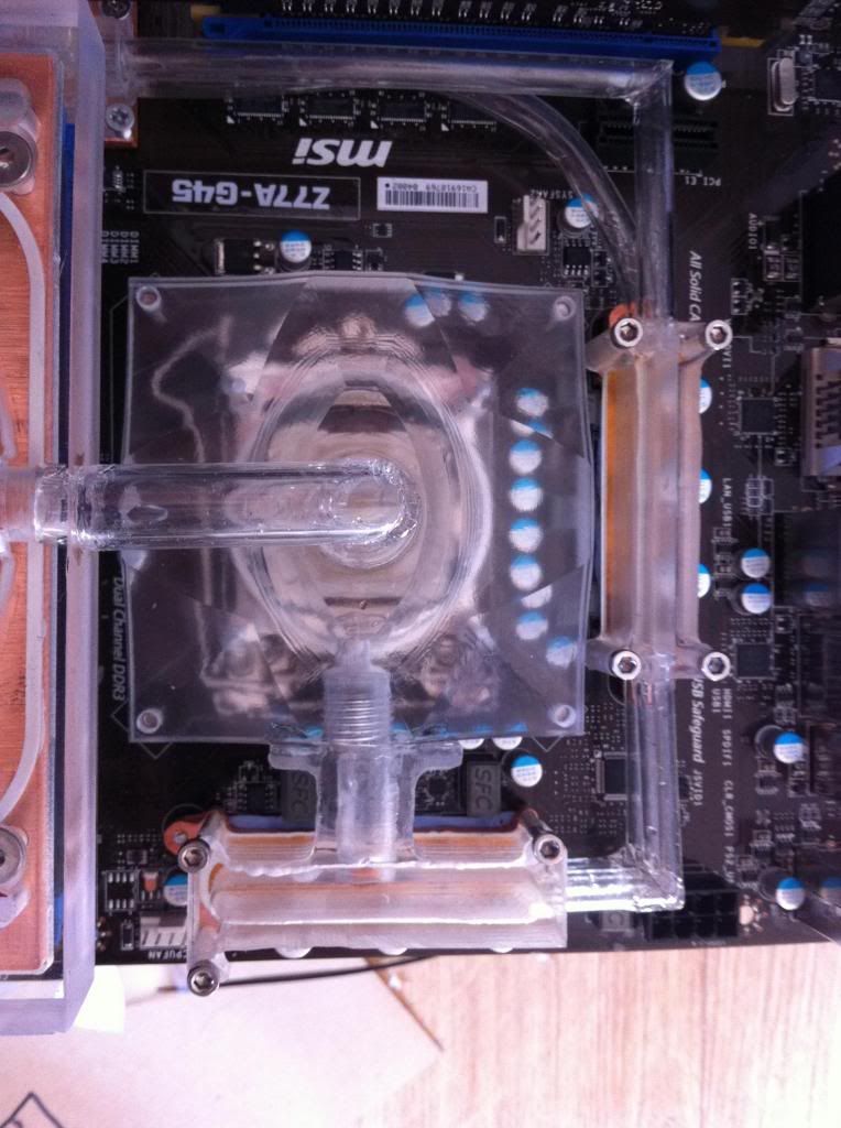
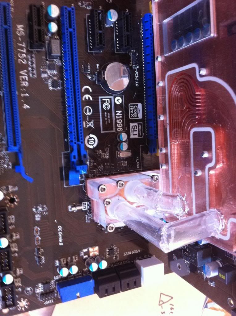
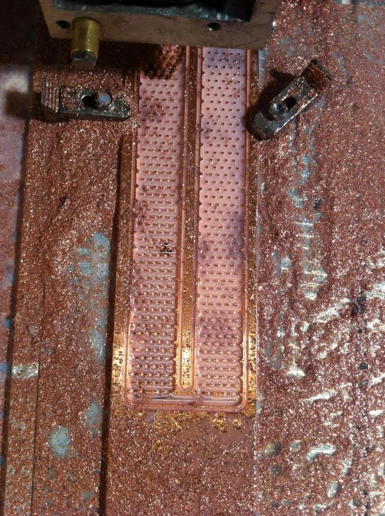
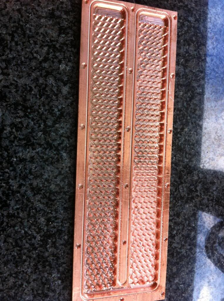
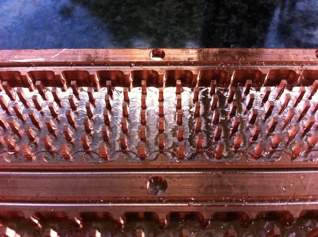
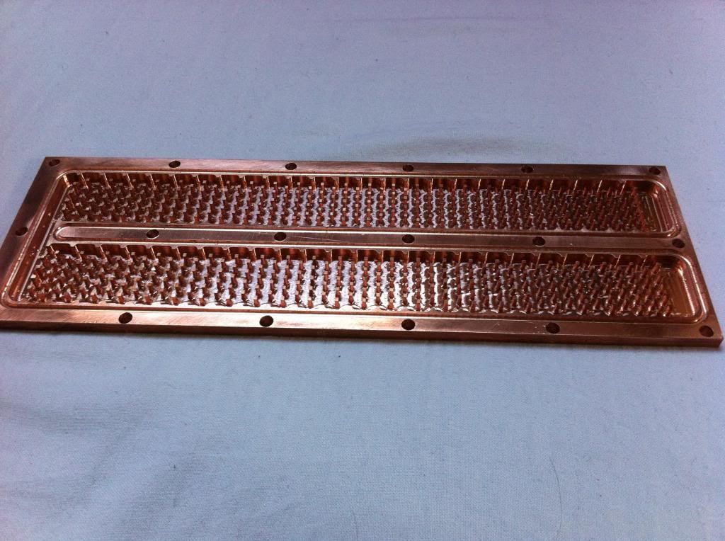
I wanted to do something different so I designed my own water block for the cpu. the biggest difference is that this block does not use any matter heat transfer plate like normal cpu blocks, instead it forces the water do go directly over the ihs. this removes the disadvantage of the TIM and extra material which compensates for the loss of surface.
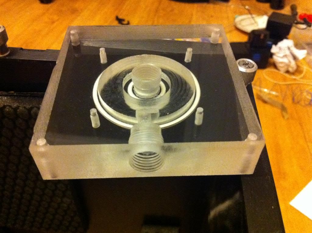
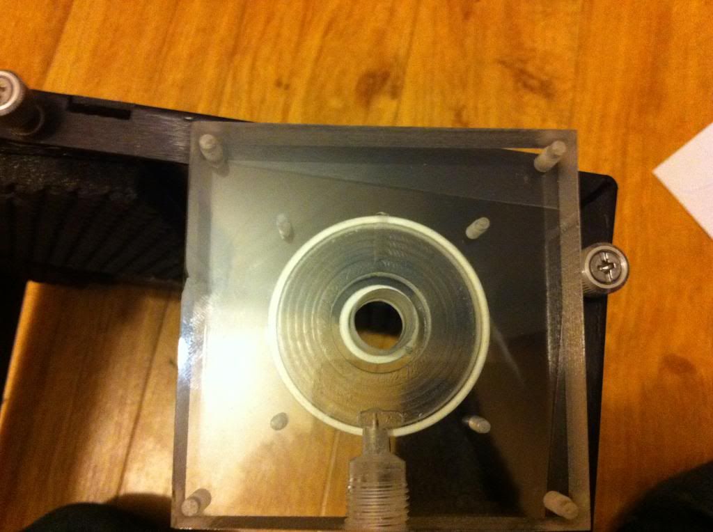
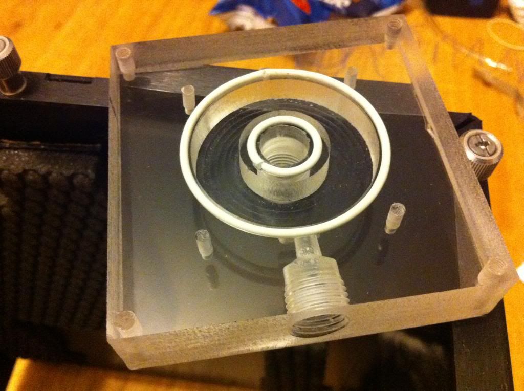
at the bottom there will be an extra plate so it's not finished jet.
---------- Post added at 15:08 ---------- Previous post was at 15:07 ----------
update 5 new top window:
as I said before the top window was not up to my standards so I redid it with better letters and this time no scratches:


update 6 cpu cooler:
I wanted to do something different so I designed my own water block for the cpu. the biggest difference is that this block does not use any matter heat transfer plate like normal cpu blocks, instead it forces the water do go directly over the ihs. this removes the disadvantage of the TIM and extra material which compensates for the loss of surface.


at the bottom there will be an extra plate so it's not finished jet.
---------- Post added at 15:10 ---------- Previous post was at 15:08 ----------
update 9 ram cooler:
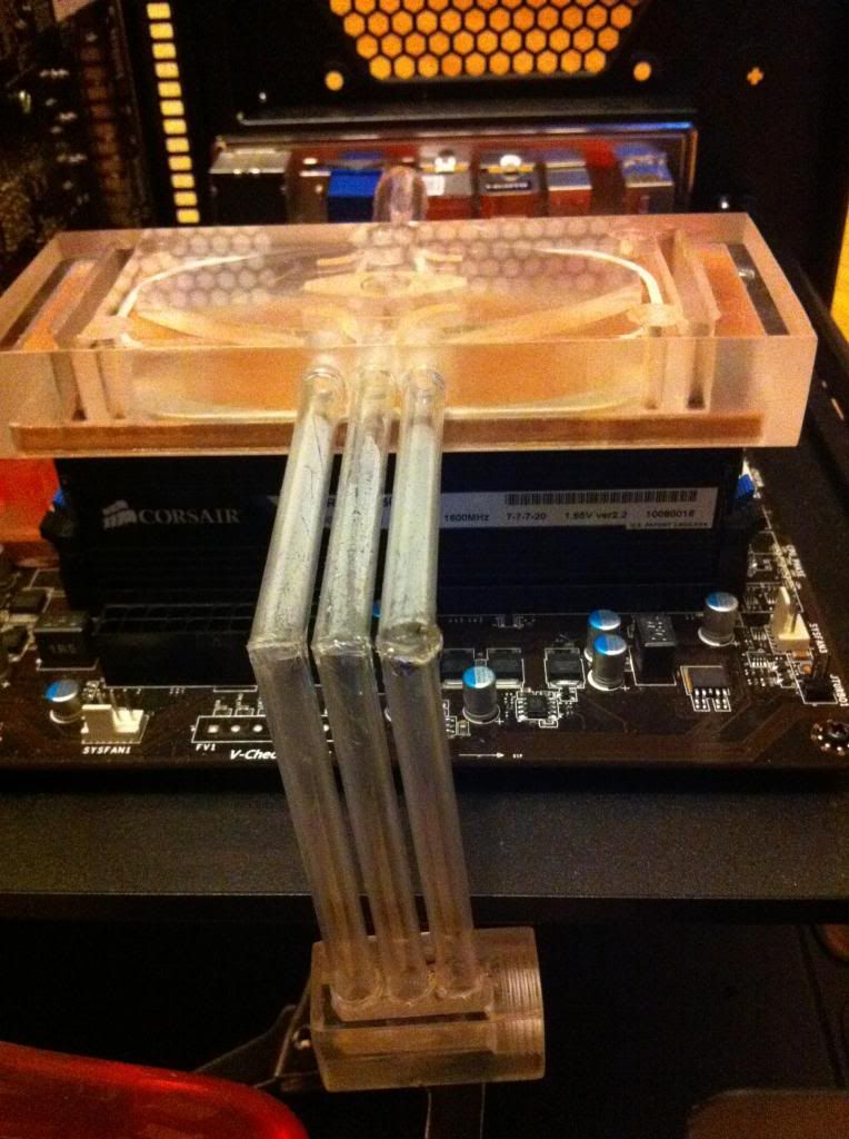
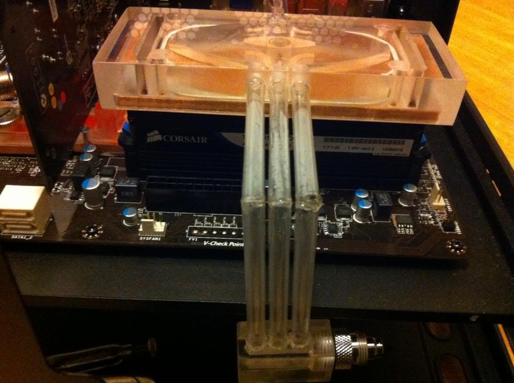
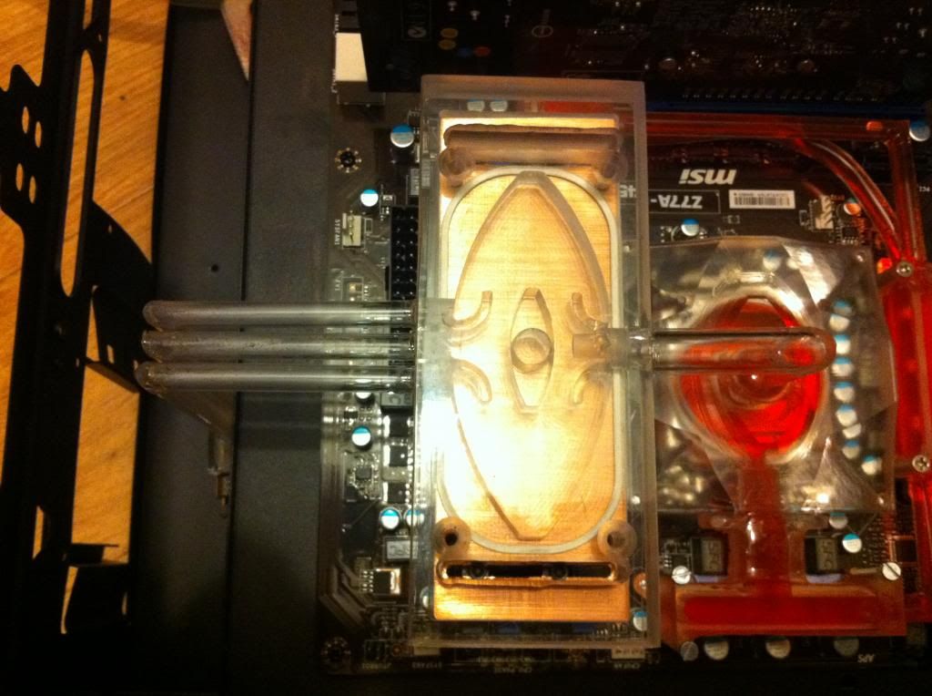
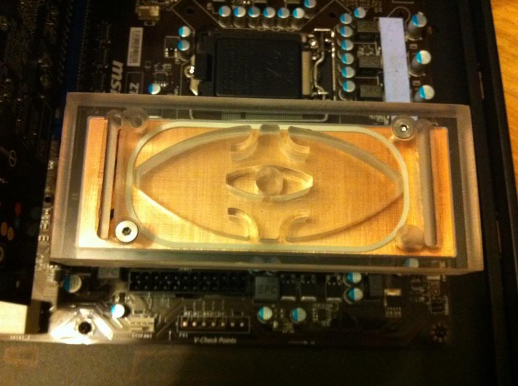
the next piece on the list is the ram cooler, I designed it for the corsair dominator series. the nice thing is that it has the inlet and outlet on the sides so no stupid tubing on the top.
first is the plexi piece:
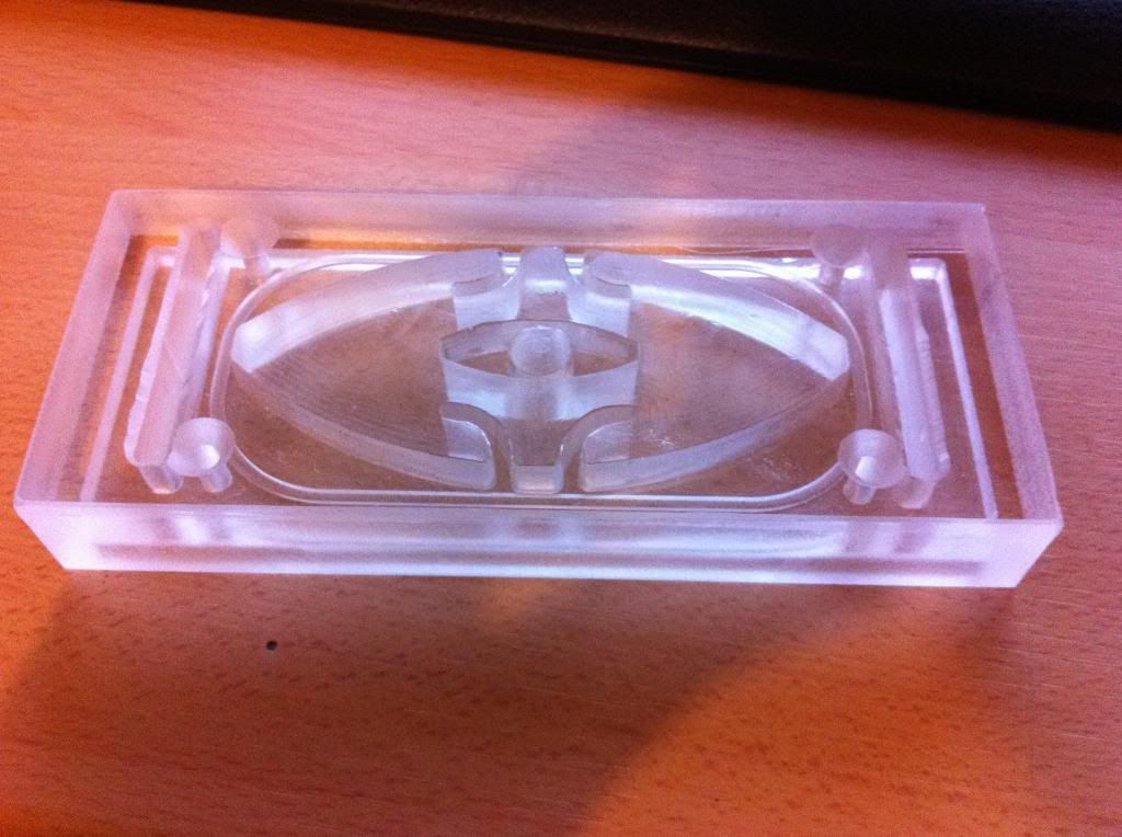
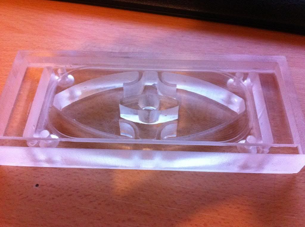
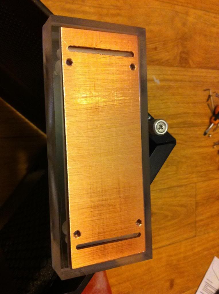
and finally the copper bottom:
as you can see the copper plate is sunk into the Plexiglas piece so it shows no copper to the sides.
the completed part:
---------- Post added at 15:10 ---------- Previous post was at 15:10 ----------
update 9 ram cooler:
the next piece on the list is the ram cooler, I designed it for the corsair dominator series. the nice thing is that it has the inlet and outlet on the sides so no stupid tubing on the top.
first is the plexi piece:


and finally the copper bottom:
as you can see the copper plate is sunk into the Plexiglas piece so it shows no copper to the sides.


the completed part:


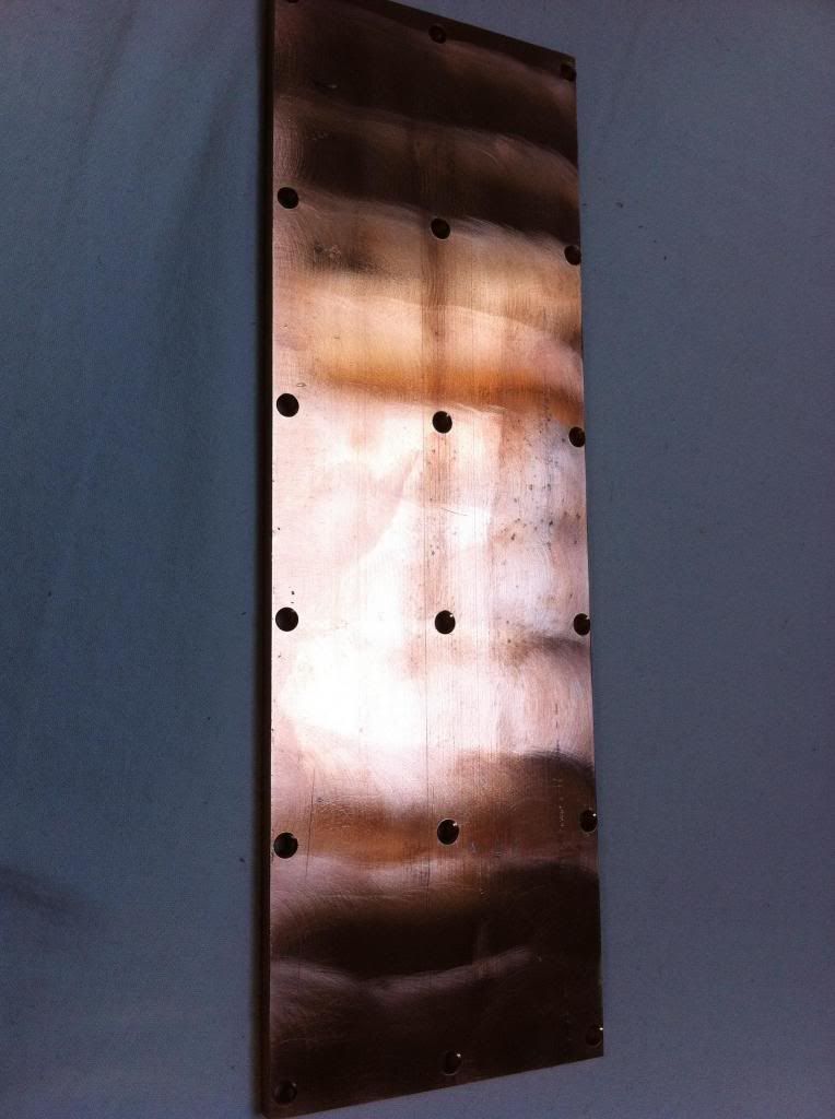
---------- Post added at 15:12 ---------- Previous post was at 15:10 ----------
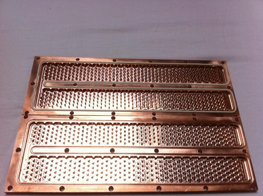
update 10 the gpu block (copper part)
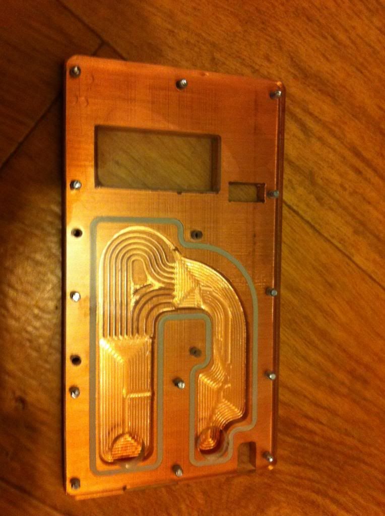
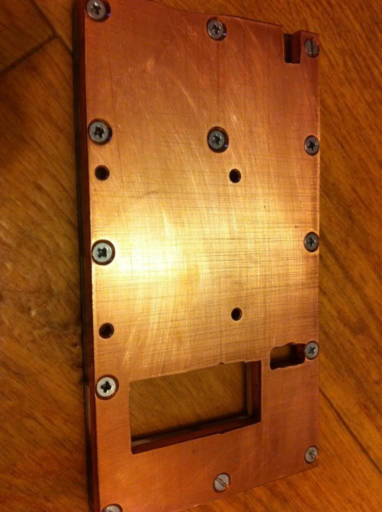
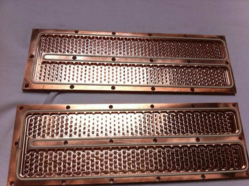
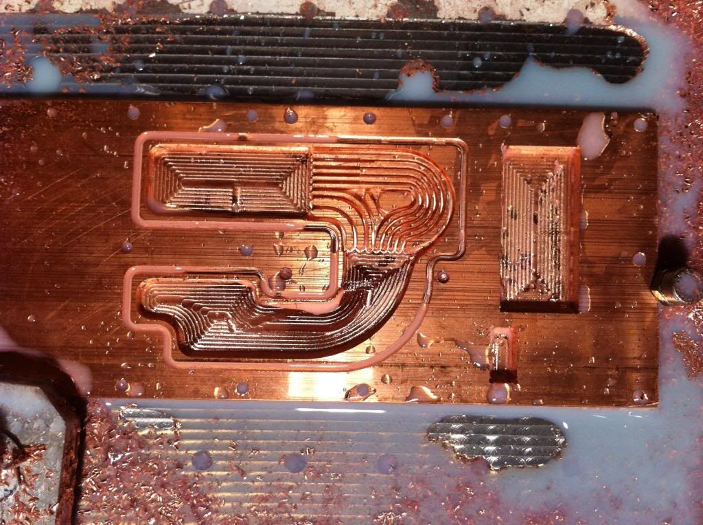
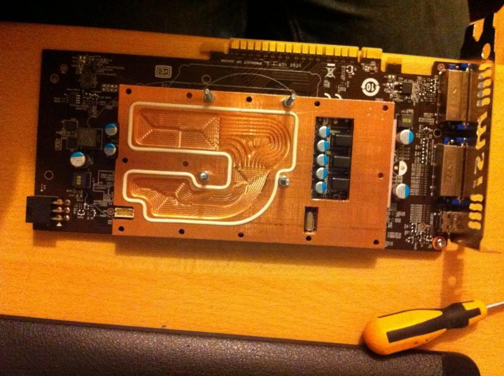
I had finished the mdf prototype and it fit nicely so now it is time to move on to the real deal:
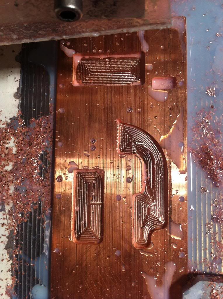
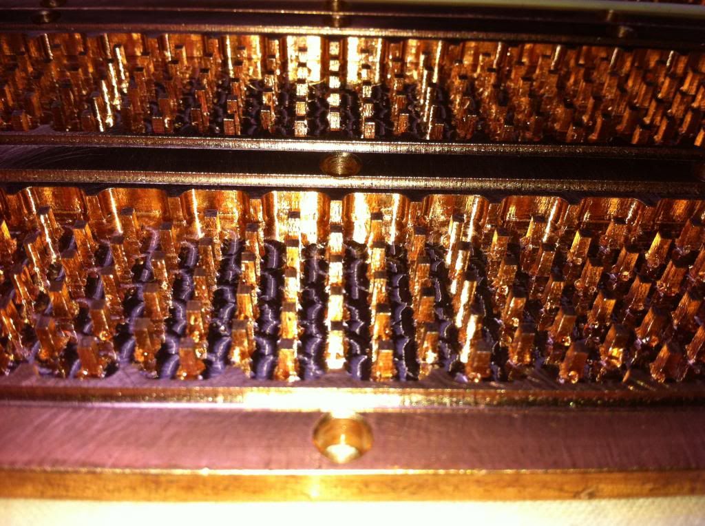
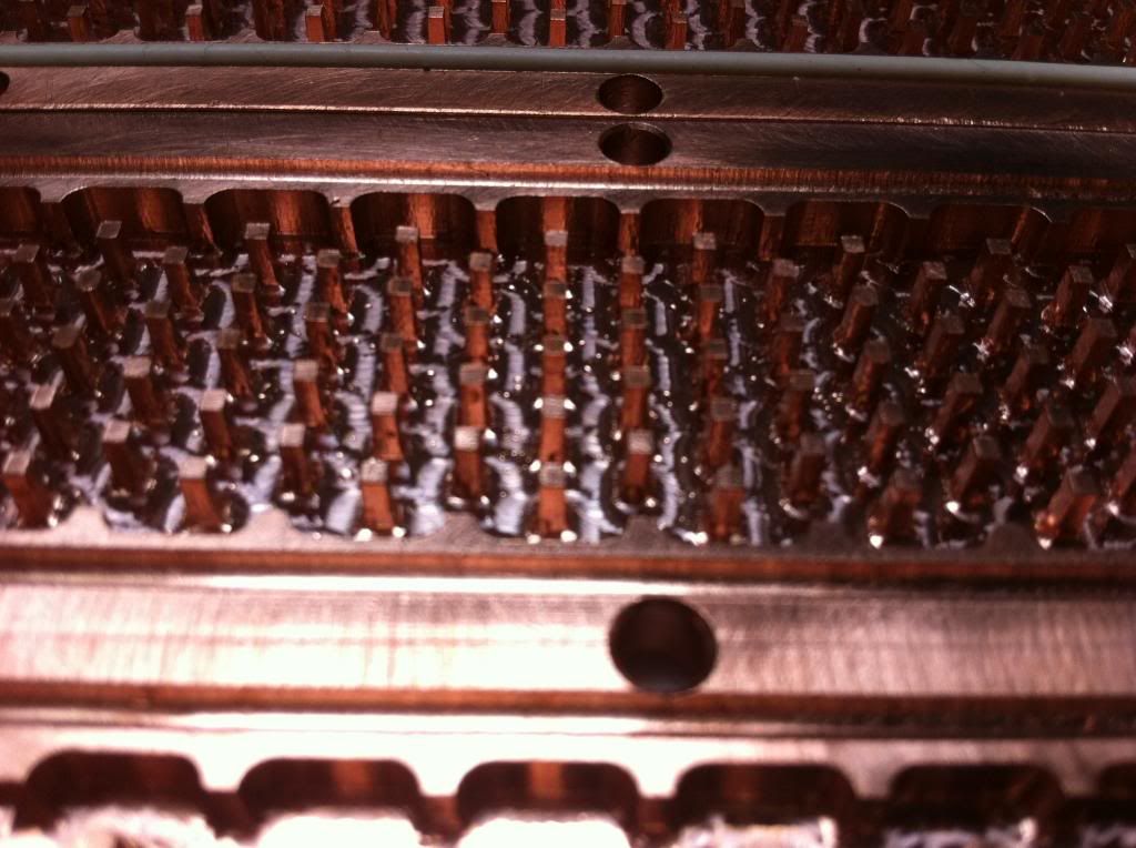
milling with a 1mm 2f end mill to make the slots:
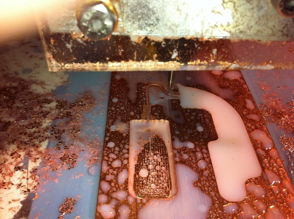
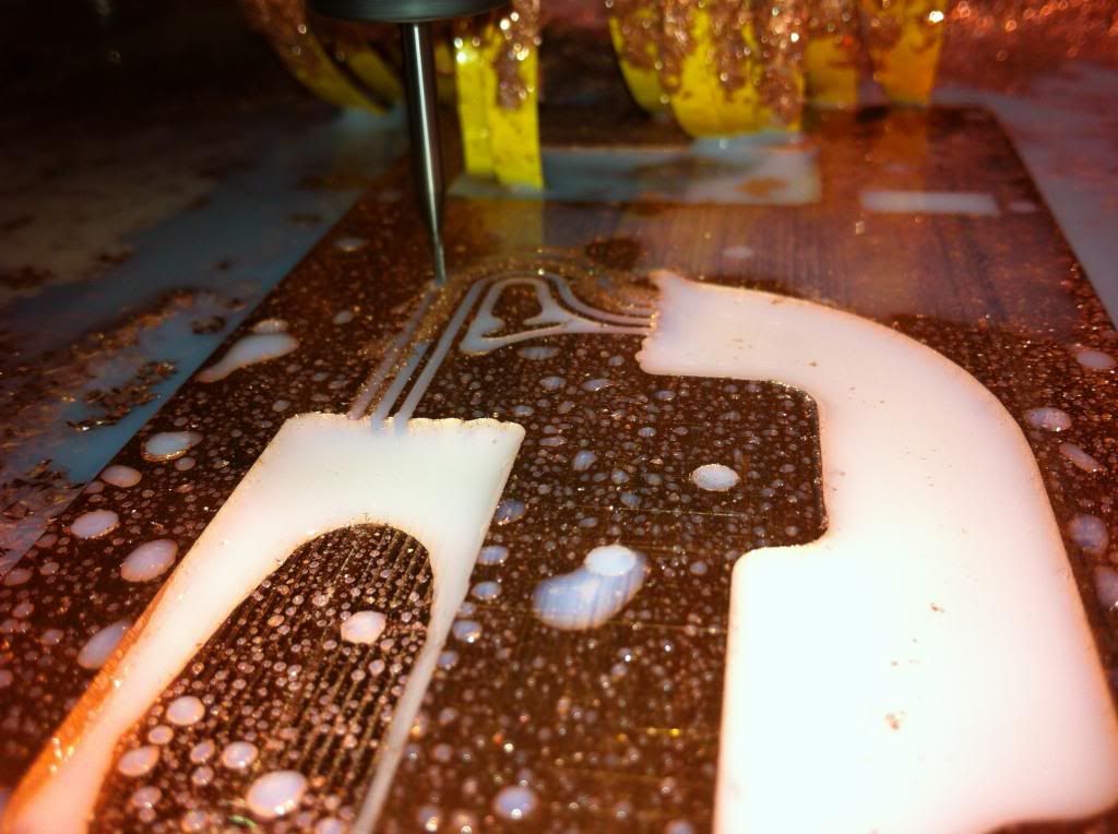
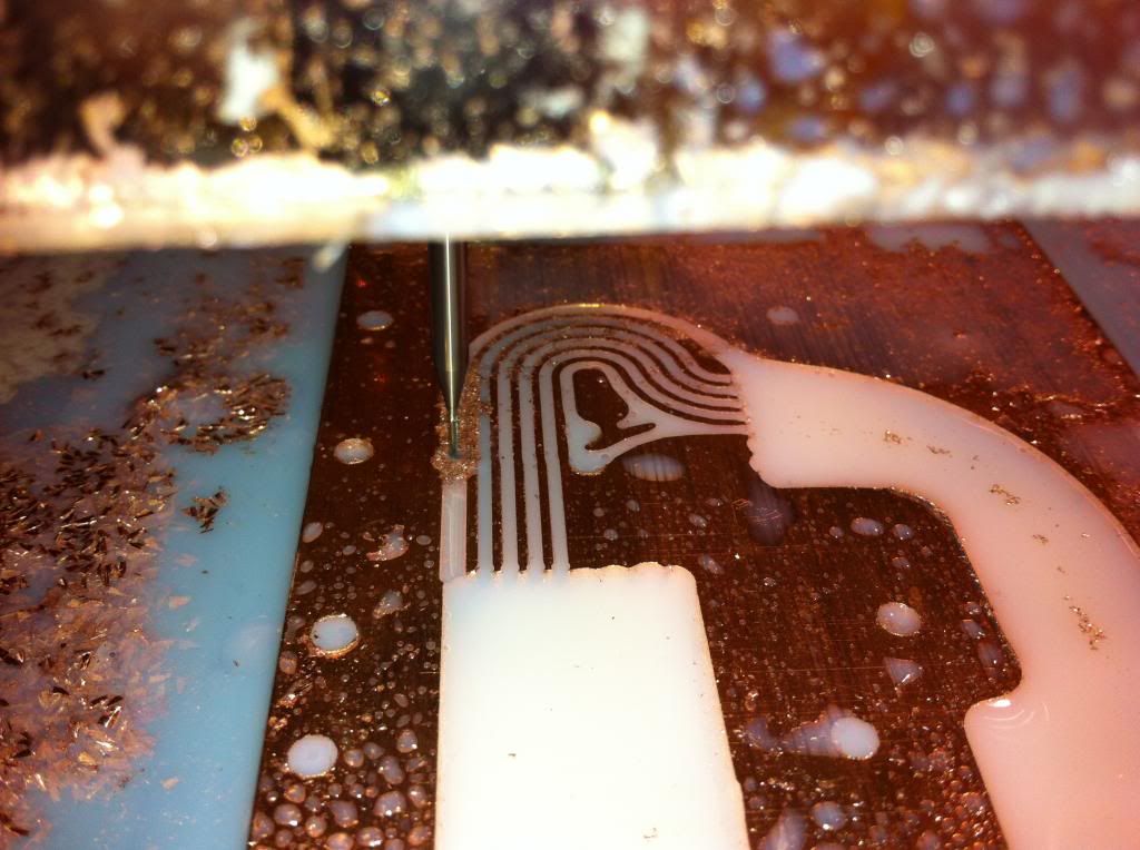
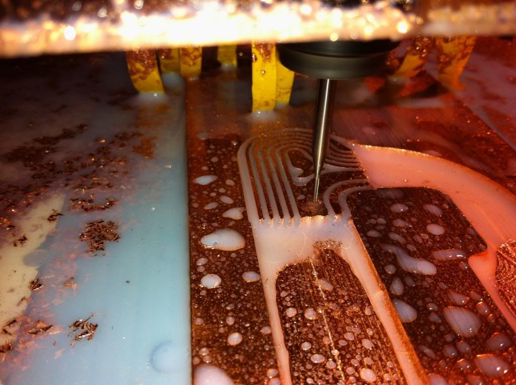
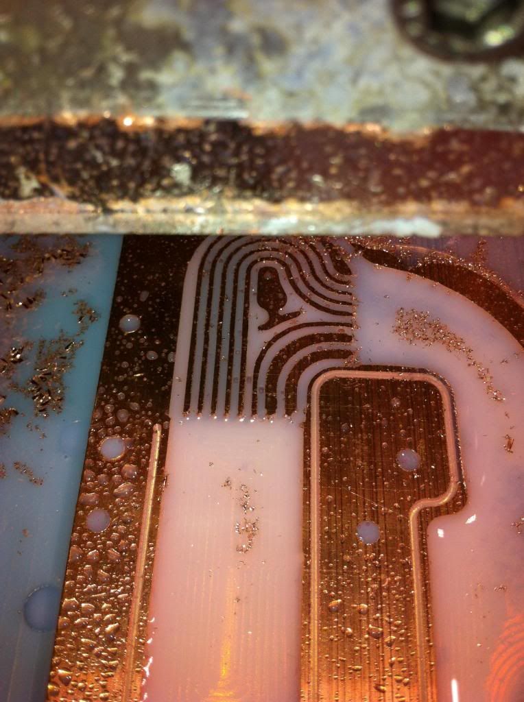
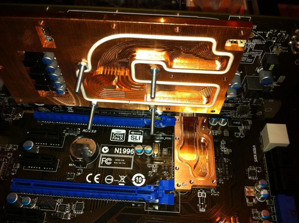
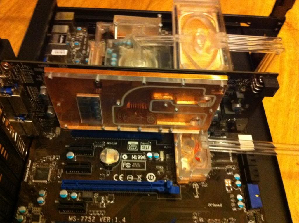
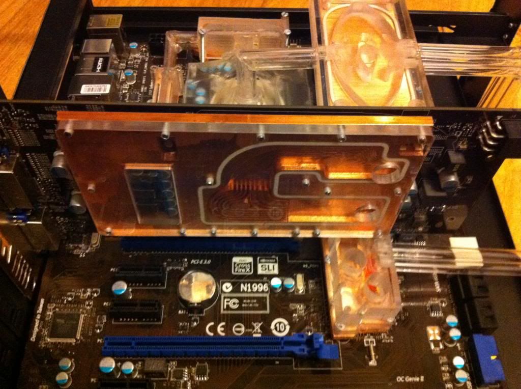
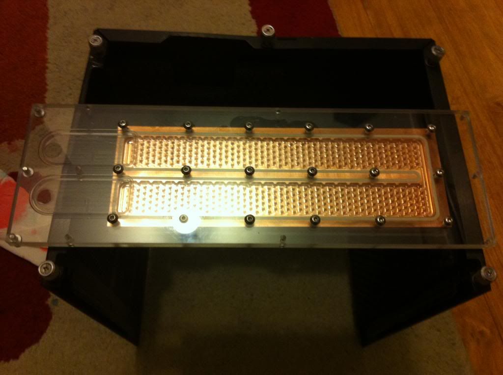
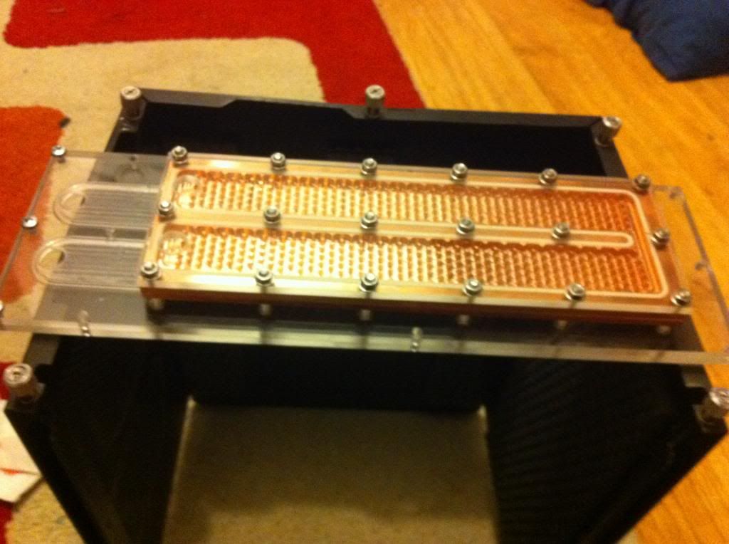
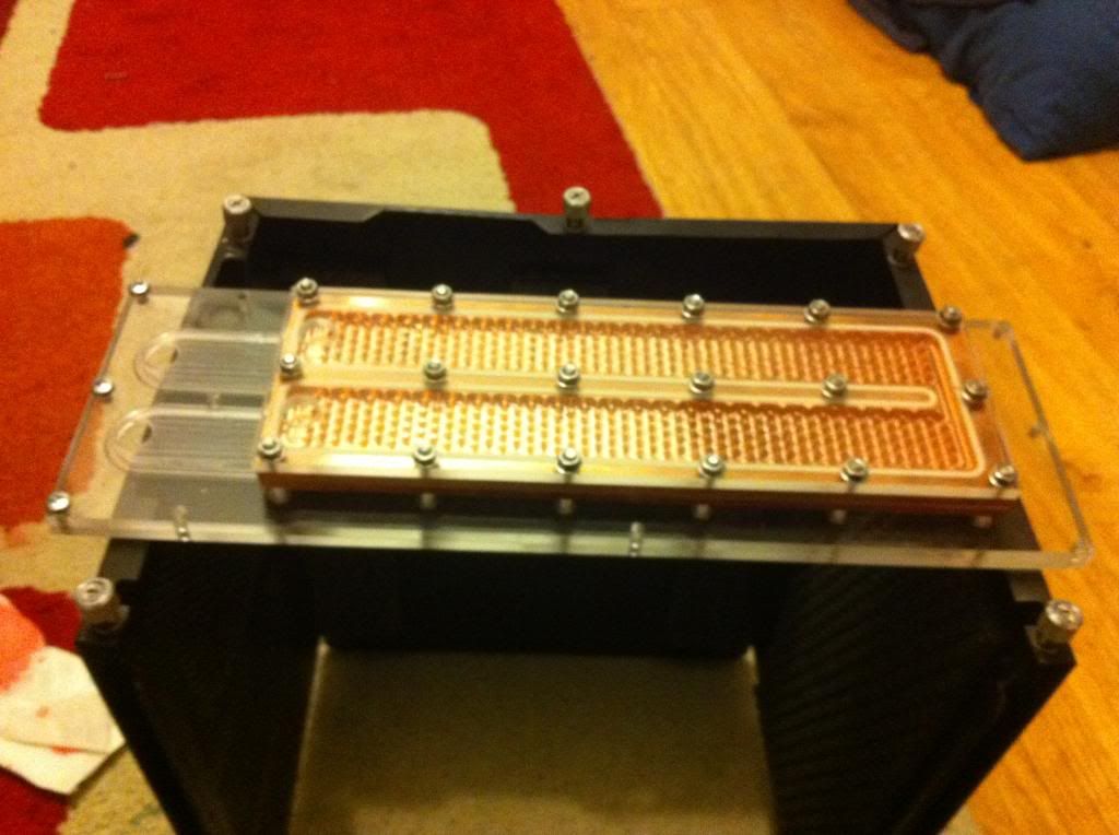
finally a test mount:
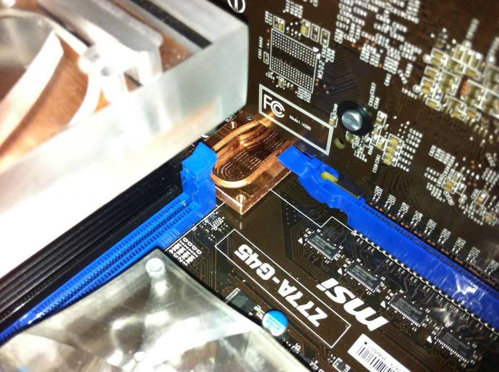
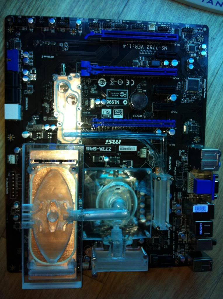
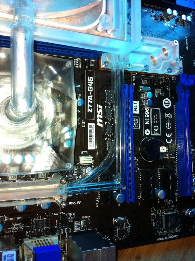
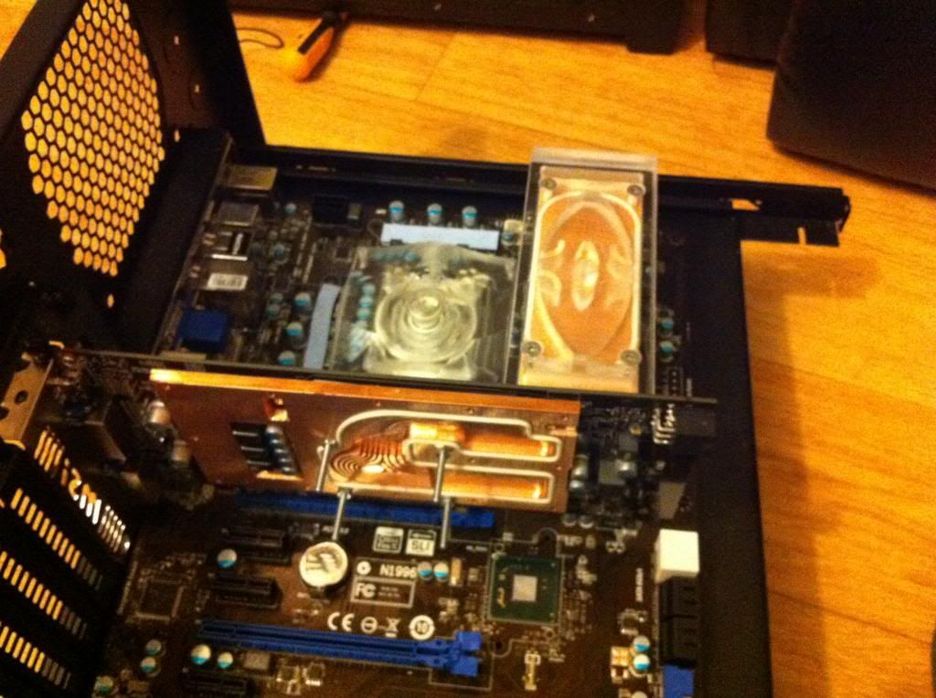
and all the made parts together:
---------- Post added at 15:13 ---------- Previous post was at 15:12 ----------
update 10 the gpu block (copper part)
I had finished the mdf prototype and it fit nicely so now it is time to move on to the real deal:

milling with a 1mm 2f end mill to make the slots:


finally a test mount:

and all the made parts together:

 because of the rules of the contest where this case was made for I could not post any pictures before the end of the contest.
unfortunataly my german is not as good as it was so that is why it is in english.
so prepare yourself for some 250+ pictures of the build I made :P
before I begin I want to show you the renders of the case, these were made with solidworks and therefore the coolant is not there like most people use in sketchup:


also a chiller was made but it had a separate build log so I'm not going to post that again. you can find it with Dutch description here: super cool
just use Google translate :P the rest of the build will be here

first of I want to start by showing everybody the tools I used during this build:
my drills:

my end mills:

the belt an disk sander:

my el cheapo disk grinder:

ferm drill press:

bosch blue jigsaw:

my self designed and build cnc machine(700mmx550mm range)


---------- Post added at 15:03 ---------- Previous post was at 15:02 ----------
update 1 goodies arrive:
I think this is rather self explanatory.
first the msi stuff:


and the cooler master parts:


---------- Post added at 15:03 ---------- Previous post was at 15:03 ----------
update 1 goodies arrive:
I think this is rather self explanatory.
first the msi stuff:


and the cooler master parts:


---------- Post added at 15:05 ---------- Previous post was at 15:03 ----------
update 2 mdf gpu prototype and first plexi window
I already had some sketchup file of the graphics card so with a little adjustment I started the work for the full cover gpu block. of course first starting with a cheap material like mdf for prototype:


it took about 3 tries before I got it right, luckily it took only 2 mins of time to make a prototype

that day also the copper arrived(80*500*5mm bars)

I also made the first of 2 side windows:

update 3 the top window
I started making the top window but unfortunately it was not good enough by my standards so later on I will be redoing it, but it shows the evolving process so no harm showing it:
first prepared with a 1,5mm 1flute end mill:

next with a 3mm end mill to make the waterway and the inside of the letters:

next couple are the result:


the last one shows why I didn't use it, too many scratches and the letters are awful :P
---------- Post added at 15:05 ---------- Previous post was at 15:05 ----------
update 2 mdf gpu prototype and first plexi window
I already had some sketchup file of the graphics card so with a little adjustment I started the work for the full cover gpu block. of course first starting with a cheap material like mdf for prototype:


it took about 3 tries before I got it right, luckily it took only 2 mins of time to make a prototype

that day also the copper arrived(80*500*5mm bars)

I also made the first of 2 side windows:

update 3 the top window
I started making the top window but unfortunately it was not good enough by my standards so later on I will be redoing it, but it shows the evolving process so no harm showing it:
first prepared with a 1,5mm 1flute end mill:

next with a 3mm end mill to make the waterway and the inside of the letters:

next couple are the result:


the last one shows why I didn't use it, too many scratches and the letters are awful :P
---------- Post added at 15:06 ---------- Previous post was at 15:05 ----------
update 4 start of the reservoir:
first I will show you the materials I got that day:
the biggest piece is 5mm 100x50cm next biggest is 20mm thick and will be used for the cpu cooler, ram cooler, mosfet cooler and the Southbridge cooler. the last piece will be used for the reservoir's(there are 2)

also some acrylic pipes(12mm and 7mm)


in the evening I started milling the reservoir, first part was done with a 8mm 1f end mill:
it is going to be a 2 part reservoir that is combined into one.


the finished first piece:


next I made the white acrylic top plate for the middle reservoir:


finally I made the top plate of the outside reservoir:


as you can see there are 5 inlets/outlets on the reservoir, this is done because the water can go in front of the middle reservoir via the sling, but this can be very restrictive so I made a parallel line with a valve to be able to regulate the flow.
here are some pictures of the res with some fluid inside(this is not the final fluid)


---------- Post added at 15:06 ---------- Previous post was at 15:06 ----------
update 4 start of the reservoir:
first I will show you the materials I got that day:
the biggest piece is 5mm 100x50cm next biggest is 20mm thick and will be used for the cpu cooler, ram cooler, mosfet cooler and the Southbridge cooler. the last piece will be used for the reservoir's(there are 2)

also some acrylic pipes(12mm and 7mm)


in the evening I started milling the reservoir, first part was done with a 8mm 1f end mill:
it is going to be a 2 part reservoir that is combined into one.


the finished first piece:


next I made the white acrylic top plate for the middle reservoir:


finally I made the top plate of the outside reservoir:


as you can see there are 5 inlets/outlets on the reservoir, this is done because the water can go in front of the middle reservoir via the sling, but this can be very restrictive so I made a parallel line with a valve to be able to regulate the flow.
here are some pictures of the res with some fluid inside(this is not the final fluid)


---------- Post added at 15:07 ---------- Previous post was at 15:06 ----------
update 5 new top window:
as I said before the top window was not up to my standards so I redid it with better letters and this time no scratches:


update 6 cpu cooler:
I wanted to do something different so I designed my own water block for the cpu. the biggest difference is that this block does not use any matter heat transfer plate like normal cpu blocks, instead it forces the water do go directly over the ihs. this removes the disadvantage of the TIM and extra material which compensates for the loss of surface.


at the bottom there will be an extra plate so it's not finished jet.
---------- Post added at 15:08 ---------- Previous post was at 15:07 ----------
update 5 new top window:
as I said before the top window was not up to my standards so I redid it with better letters and this time no scratches:


update 6 cpu cooler:
I wanted to do something different so I designed my own water block for the cpu. the biggest difference is that this block does not use any matter heat transfer plate like normal cpu blocks, instead it forces the water do go directly over the ihs. this removes the disadvantage of the TIM and extra material which compensates for the loss of surface.


at the bottom there will be an extra plate so it's not finished jet.
---------- Post added at 15:10 ---------- Previous post was at 15:08 ----------
update 9 ram cooler:
the next piece on the list is the ram cooler, I designed it for the corsair dominator series. the nice thing is that it has the inlet and outlet on the sides so no stupid tubing on the top.
first is the plexi piece:


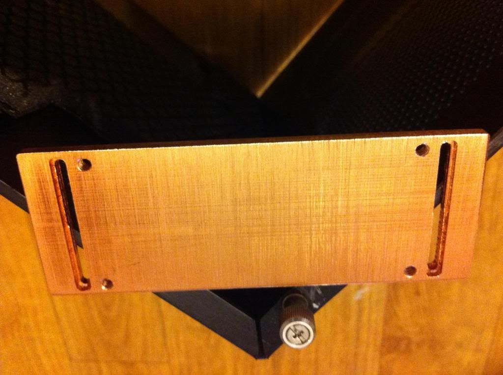
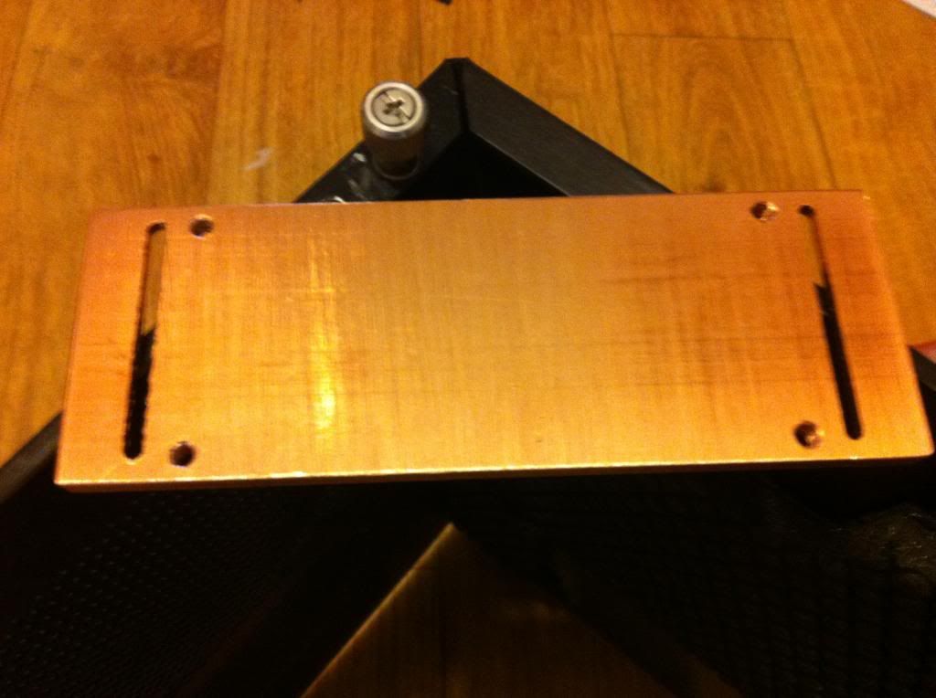
and finally the copper bottom:
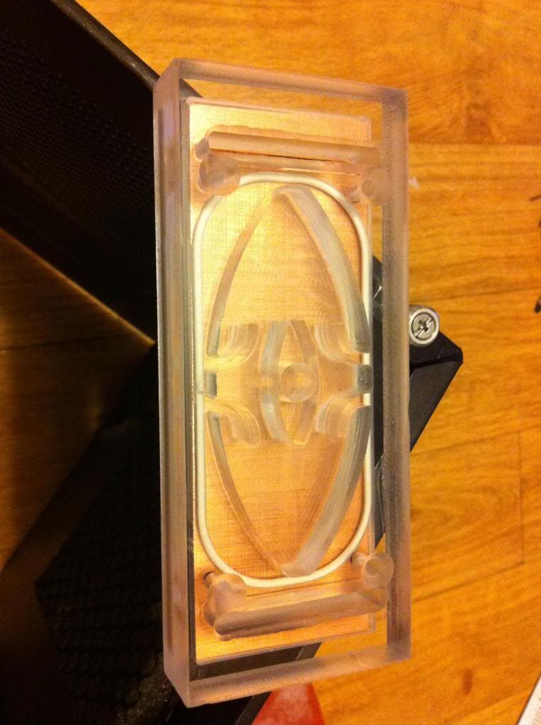
as you can see the copper plate is sunk into the Plexiglas piece so it shows no copper to the sides.


the completed part:


---------- Post added at 15:10 ---------- Previous post was at 15:10 ----------
update 9 ram cooler:
the next piece on the list is the ram cooler, I designed it for the corsair dominator series. the nice thing is that it has the inlet and outlet on the sides so no stupid tubing on the top.
first is the plexi piece:


and finally the copper bottom:
as you can see the copper plate is sunk into the Plexiglas piece so it shows no copper to the sides.


the completed part:


---------- Post added at 15:12 ---------- Previous post was at 15:10 ----------
update 10 the gpu block (copper part)
I had finished the mdf prototype and it fit nicely so now it is time to move on to the real deal:

milling with a 1mm 2f end mill to make the slots:


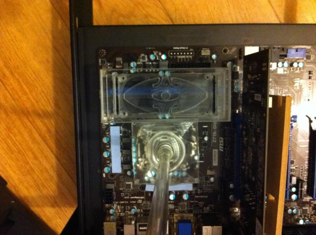
finally a test mount:

and all the made parts together:

---------- Post added at 15:13 ---------- Previous post was at 15:12 ----------
update 10 the gpu block (copper part)
I had finished the mdf prototype and it fit nicely so now it is time to move on to the real deal:

milling with a 1mm 2f end mill to make the slots:


finally a test mount:

and all the made parts together:


