AGP-VDDQ Src: +3.33v
North Bridge Voltage Src: +3.33v
agp Mod is By Pin 2 (Inverting Input A) on the LM358
;;;;;;
RS232-DB9 COM/Serial Port: Doesn't Use Power
RS232-DB25 LPT/Printer Port: +5.00v
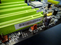
AGP Slot: +12.00v, +5.00v, +3.33v, AGP-VDDQ
PCI Slot: +12.00v, -12.00v, +5.00v, +3.33v
;;;;;;
Supposedly R151 is For The South Bridge Voltage Mod.
R151 is a 0k Resistor
Reads back as:
LM3580
Memory Voltage Controller: Semtech SC2616
VDDQ Mod: 100k Pot
CMOS EEPROM: ATMEL 24C32AN
;;; Notes:
DMM of 0.7% accuracy.
Ground accuracy of 0.02v given the stock psu I'm using, however in practice it was actually 0% (un-meassurable when used with a +).
I always used a ground from the psu, incase the float was a diff level on the board's grounds.
;;; Resistors
R156: 102 North Bridge Voltage Regulator Feedback (Offset)
R192: 10d Memory VDDQ Feedback
R186: 25C Memory VDDQ+VTT (Lower Resitance = More Voltage Output)
R198: 30C Memory VDDQ of some sort
MEM-VDDQ -> R198 -> R186 -> Ground ... Pencil R186 For MEM-VDDQ+MEM-VTT Mod
;;;
+5.00v -> Q26 -> Q23 -> MEM-VDDQ(RAW) & Q21
Q21 -> SC2616 Pin: BG
BG = Bottem Gate Drive
;;; Caps:
C3C2: 100uf 16v
C3E2: 100uf 16v
C5C3 (Missing): ? +3.33v
C5E3 (Missing): ? +5.00v
C5F2 (Missing): ?
C6C1: 470uf 16v +12.00v
C6C2: 10uf 16v
C6D3: 10uf 16v
C8C7: 10uf 16v
C11J2: 10uf 16v
EC3 (Missing): ? ? 2.40v+, same thing as EC65, measured resistance, probably will prevent the board form booting if a cap is placed there, then again there are caps in place by stock that do the same thing...
EC4: 10uf 16v
EC5: 100uf 16v
EC6: 100uf 16v
EC7: 100uf 16v
EC8 (Missing): ? +12.00v
EC9: 10uf 16v
EC10: 470uf 16v +5.00v
EC11: 470uf 16v +5.00v
EC12: 10uf 16v
EC13: 1500uf 16v +12.00v
EC14: 22uf 25v (AB0, Couldn't read on AC0)
EC15: 3300uf 6.3v CPU-VDD
EC16 (Missing): ? +12.00v
EC17: 100uf 16v
EC18 (Missing): ? +12.00v
EC19 (Missing): ? +3.33v
EC20: 3300uf 6.3v CPU-VDD
EC21: 1500uf 16v +12.00v
EC22: 1500uf 16v +12.00v
EC23: 3300uf 6.3v CPU-VDD
EC25 (Missing): ? +3.33v
EC24: 10uf 16v
EC26: 100uf 16v
EC27: 10uf 16v
EC29 (Missing): ? +5.00v
EC2d: 100uf 16v
EC30: 100uf 16v
EC31 (Missing): ? +3.33v
EC32 (Missing): ? +5.00v
EC33: 3300uf 6.3v CPU-VDD
EC34 (Missing): ? +3.33v
EC35 (Missing): ? +5.00v
EC36: 3300uf 6.3v CPU-VDD
EC37: 1000uf 10v +5.00v
EC38 (Missing): ? +12.00v
EC40: 100uf 16v
EC41 (Missing): ? +3.33v
EC42: 10uf 16v Supposedly The South Bridge Voltage, 1.62v
EC43: 1000uf 6.3v AGP VDDQ (Main Cap)
EC44 (Missing): 10uf 16v ??? North Bridge Regulated Output, Hooks into the regulator chip, Used for smoothing out the regulator a bit, dn if it works
EC45: 10uf 16v
EC46: 10uf 16v
EC47: 1000uf 6.3v North Bridge Regulated Output (Main Cap)
EC50: 1000uf 6.3v MEM VDDQ
EC52 (Missing): 10uf 16v ??? North Bridge Regulated Output, to smooth out the fluctuations if any (there is by that point on the board).
EC53: 470uf 16v +5.00v
EC54 (Missing): ? +12.00v, probably for the SC2616.
EC55: 470uf 6.3v +3.33v
EC56: 1000uf 6.3v MEM VDDQ
EC57 (Missing): ? MEM VTT & VTT-Sense (VTT is tied directly to VTT-Sense unfortunatly..., there is no way of adjusting it separately without cutting the trace from under the board and redoing it)
EC59: 220uf 10v MEM VTT
EC60: 1000uf 10v +5.00v (Assumed MEM VDDQ Src)
EC61 (Missing): ?
EC62: 220uf 10v MEM VTT
EC63 (Missing): 4.7uf 16v ??? MEM VDDQ & ATMEL 24C32AN (CMOS / CMOS Reloaded) (From what it looks like, it looks like it's only for the CMOS)
EC64: 1000uf 10v +5.00v (Assumed MEM VDDQ Src)
EC65 (Missing): ? +5.00v, Supposedly (trodas) if you put a cap here the board won't post, Note that if measured resistance against ground it opens then closes immediately, hence to say it will prevent the board from starting up probably
EC66: 220uf 10v MEM VTT
EC67: 1000uf 6.3v MEM VDDQ
EC68: 220uf 10v MEM VTT
EC69: 1000uf 6.3v ??? Read 1.86v
CPU-VDD Source: EC13, EC21, EC22
Stock: 3x 1500uf (4500uf)
Better: 3x ??? (Using 1800uf for now)
Notes:
1800uf seems worse, but the better caps allow me to use lower vcore values and have them actually work... (only if the cpu speed is low enough)
CPU-VDD: EC15, EC20, EC23, EC33, EC36
Stock: 5x 3300uf (16500uf)
AGP-VDDQ: EC43
Stock: 1x 1000uf
NB-Voltage: EC47
Stock: 1x 1000uf
Better: 1x 1800uf
Notes:
Stability increased in memory timings and bus timings.
Stability increased by a decent amount with lower nb voltages.
Overall bandwith and stability increases.
MEM-SRC: EC60, EC64
Stock: 2x 1000uf (2000uf)
DataSheet: 3x 1500uf (4500uf)
MEM-VTT: EC59, EC62, EC66, EC68
Stock: 4x 220uf (880uf)
DataSheet: 1x 1500uf
MEM-VDDQ: EC50, EC56, EC67
Stock: 3x 1000uf (3000uf)
Better: 3x 1800uf (5400uf)
DataSheet: 2x 3300uf (6600uf)
Notes:
Big improvements in load, ie 2x512m is allmost like 1x512m.
Bandwith and stability overall is slightly higher.
CPU-VDD is less dependant on memory load and config types.
;;;
;;; Coils:
LC5: MEM-VDDQ, Offset: -0.1v
;;;
;;; North Bridge Readings:
Q18: (Regulator)
BIOS: Actual
1.6v: 1.62v
1.7v: 1.73v
1.8v: 1.83v
1.9v: 1.94v
EC52: (After Fet)
BIOS: Actual
1.6v: 1.62v
1.7v: 1.73v
1.8v: 1.83v
1.9v: 1.94v
EC44: (After Fet, way after...)
Seemed lower then the last cap...
1.72v I believe.
Read the Regulator by reading off the leg towards the bottom, next to the board's screw hole (MH6).
;;;
;;; AGP Readings:
Q12: AGP Regulator
Src: +3.33v
BIOS: Actual (BIOS VAGP Setting Thingy)
1.5v: 1.54v
1.6v: 1.64v
1.7v: 1.74v
1.8v: 1.84v
Measure by top leg, closest to agp slot.
;;;
;;; MEM Readings:
Q21: VDDQ Regulated Final Output To Memory.
BIOS: Actual (BIOS VDDQ Setting)
2.6v: 2.60v
2.7v: 2.71v
2.8v: 2.80v
2.9v: 2.91v
3.0v: 3.00v
3.1v: 3.09v
3.2v: 3.19v
3.3v: 3.29v
Q23: VDDQ Regulated Output To Q21.
BIOS: Actual (BIOS VDDQ Setting)
2.6v: 2.63v
2.7v: 2.72v
2.8v: 2.82v
2.9v: 2.92v
3.0v: 3.01v
3.1v: 3.10v
3.2v: 3.18v
3.3v: 3.29v
Q26: ??? (Seems like Regulated Rail To Q23, not sure yet)
Measure Q21 By it's base.
Measure Q23 By the leg closest to Q21.
Update!: I apparently have no idea how to really measure those mem fets, neither does anyone else...
Go by the darn caps on the board, there's a huge diff!, I'd otherwise go by the fets if I knew how they were configured and how to read them.
Also note that it's about equal with VTT that way, now it makes sense...
Also that's why mbm reads it way off, like it should apparently, when sensor is *0.016 (I dn if that calculation for the sensor is correct though).
EC63: (Missing cap, VDDQ, It's inbetween slots 1+2 (farthest and 2nd farthest away from chipset, ie labled slot 2+3 on the board)
BIOS: Actual (BIOS VDDQ Setting)
2.6v: 2.68v
2.7v: 2.79v
2.8v: 2.88v
2.9v: 2.99v
3.0v: 3.08v
3.1v: 3.18v
3.2v: 3.28v
3.3v: 3.39v
EC57: MEM VTT / VTT-Sense
BIOS: Actual (BIOS VDDQ Setting)
2.6v: 1.35v
2.7v: 1.4v
2.8v: 1.45v
2.9v: 1.5v
3.0v: 1.54v
3.1v: 1.6v
3.2v: 1.65v
3.3v; 1.7v (note a 3.4v vddq would be for this vtt if it was a stock 1/2 setup, it's making sense now, mobo overvolts by 0.1v and doesn't tell you...)
MEM FeadBack (VDDQ-Sense) Readings: (Via After Resistor just before the pin on the SC2616)
BIOS: Actual
2.6v: 1.27v
2.7v: 1.27v ...
Wth you know...
That's not how the bios is setting voltage, it is using it as a slight offset though.
That would be my guess.
What the heck though.
I dn understand yet...
;;;
R186: Black 25C
Around 9.5k stock resistance, I think (9.49k, left ground)
MEM-VDDQ & MEM-VTT Pencil Mod
You can max the VTT and VDDQ this way..., and I mean max...
8.87k = 2.87v
I want something inbetween these 2 values...
8.75k = 2.92v
8.49k = +0.4v
Supposedly it's an 18.2k resistor
25 = 178
C = 100
= 17800, 17.8k
Code:
;;; Intersil HIP6301CB
Default-Spec: 1.1v-1.85v
Default: 1.1v-2v (1.25v-2v?)
VSEN:
-10% of VCORE
Causes Power Good To Go Low.
+15% of VCORE
Causes CPU power shutdown until VCORE is lower then +15% then set VID.
;;;
vcore mod by fb to ground
ocp mod
Phillips LM3580
CSI 93C46S
0340H
Texas Instruments GD75232
39K
FR95




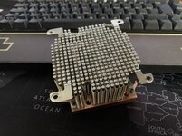

 In den USA bekommst ja einige, aber nicht zu den Versandkosten..
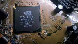
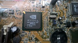

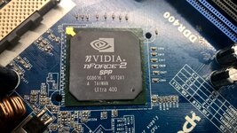

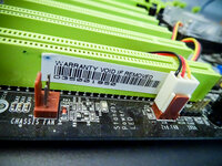
 selbst an eins zu kommen ist schon Glück…


