Award & Intel X58 Debug Codes:
The most common Debug codes, what they mean, and how to work with them.
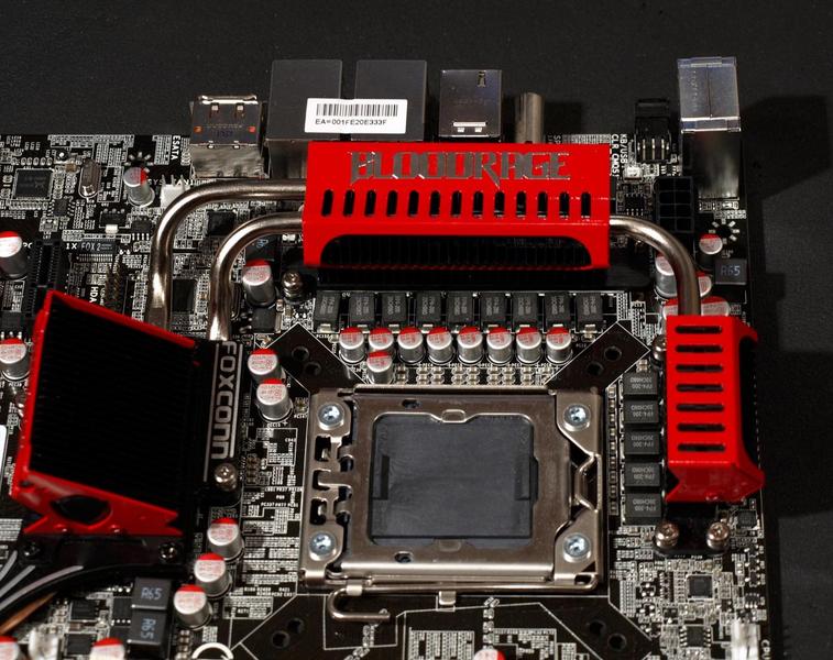
This Guide is intended for the Foxconn QuantumForce BloodRage board, but the codes should be identical or very similar on all Mainboards with Award BIOSes (Gigabyte, DFI, etc)
no LED all fans spinning
If the Board powers on with all fans spinning and all LEDs running but the DEBUG display doesnt display any POST codes and nothing else happens, then the PWM probably cant get enough juice, there is no cpu installed or the installed cpu is damaged, broken, or not supported. But check if the 8Pin 12V plug and the 24Pin ATX PSU power plugs are plugged in properly, make sure they dont bend too much or haven a lose cable. Check another PSU if possible. If nothing helps, power off the mainboard, switch the vbat discharge jumper on the bottom left of the board to disconnect the battery and wait a few minutes, then set it back to default and power the mainboard on again. The default position for this jumper is 1-2, meaning the jumper should cover the left and middle pin.
board shuts down, Debug LED flashes for half a second
If the Board powers on when you push the power button but shuts off almost immediatly after that, and the debug LED display flashed for a fraction of a second, then check if the 8Pin 12v plug and the 24Pin ATX PSU power plugs are connected properly. Make sure the board doesnt bend too much and check another psu if possible. If nothing helps, power off the mainboard, switch the vbat discharge jumper on the bottom left of the board to disconnect the battery and wait a few minutes, then set it back to default and power the mainboard on again. The default position for this jumper is 1-2, meaning the jumper should cover the left and middle pin.
E8 -> 01 -> b2 -> 00 looping
If the board powers un and keeps looping from E8 to 01 to b2 to 00 and back to E8 again, check if the memory is installed properly and try to boot with only 1 stick and try each slot individually. If one of the slots doesnt work, please power off the mainboard and psu and check if any of the pins inside the 1366 CPU socket is bent. If yes then send me a pm or contact the foxconn tech support. If the pins are alright and he memory is plugged in properly, make sure you didnt misconfigure the memory controller and set an unsupported multiplier or an unsupported combination of multipliers. Reset the bios and try again. If it still doesnt work your memory might be damaged or the SPD corrupt, or simply not supported. Please check the BloodRage memory compatibility list and send me a pm if your memory is not on the list and doesnt seem to work.
2b
When the system powers on and the Debug LED shows the usual POST code sequence but hangs on 2b or you get a beep code as soon as the sequence reaches 2b, then the Mainboard cant detect your Videocard properly. Note that the POST code sequence might not halt at 2b but continue, so the final POST Code it displays could be FF, 00 or 7F which means the Maiboard booted, entered BIOS, or OC recovery kicked in and is waiting for Input to enter BIOS. Since the Videocard couldnt be detected properly you will only see a black Monitor and either 2b, FF, 00 or 7F. Check if there is something wrong with the Videocard, the PCIE slot or BUS, the Monitor or monitor cable. Turn the Monitor on and off, switch the Monitor cable from one D-SUB or DVI plug to the other in case your Videocard has two. If this doesnt help then reboot and load the optimized defaults. If that doesnt help either try another Videocard if possible, or try the Videocard in another system to make sure its working properly. Try another monitor or try the Monitor on another System.
7F
When the system detects that a critical error happened during the last boot attempt or several boot attempts failed, so OC recovery kicked in. There should be a message displayed on the Display informing you that OC revocery kicked in and that its waiting for your input to enter BIOS. If you cant see this message cause your Display stays black, please check the description for POST Code 2b.
00
Your in the BIOS right now, if you cant see the BIOS cause your Display stays black, please check the description for POST Code 2b. If this is part of a loop please check the point "E8 -> 01 -> b2 -> 00 looping" above.
Intel MRC Code
This block of code has to be implemented in every Intel based platform BIOS. It initializes and configures the processor and runs bus training and adusting routines. It adjusts clockskews, read/write leveling, signal termination resistors and several chipset timings dynamically depending on the trace length, signal quality, timing and memory installed in the motherboard. If the MRC code hangs or the board cant pas the MRC code and resets it usually points towards memory problems and unsupported multiplier settings or a unsupported combination of multipliers.
Shut down If the board shuts down after a second and the Debug LEDs flash for a fraction of a second, the PWM cant get enough juice
7F OC Recovery
b0 Intel Core i7 MRC Code - Chipset - check above
b1 Intel Core i7 MRC Code - Chipset - check above
b2 Intel Core i7 MRC Code - Memory - check above
b3 Intel Core i7 MRC Code - CPU - check above
b4 Intel Core i7 MRC Code - Memory - check above
b5 Intel Core i7 MRC Code - CPU - check above
b6 Intel Core i7 MRC Code - Memory - check above
b7 Intel Core i7 MRC Code - Memory - check above
b8 Intel Core i7 MRC Code - Memory - check above
01 Intel Core i7 MRC Code - Memory - check above
02 Intel Core i7 MRC Code - Memory - check above
03 Intel Core i7 MRC Code - Memory - check above
04 Intel Core i7 MRC Code - Memory - check above
05 Intel Core i7 MRC Code - CPU - check above
b9 Intel Core i7 MRC Code - Memory - check above
bA Intel Core i7 MRC Code - Memory - check above
bb Intel Core i7 MRC Code - Memory - check above
bc Intel Core i7 MRC Code - Memory - check above
bd Intel Core i7 MRC Code - CPU - check above
be Intel Core i7 MRC Code - CPU - check above
bF Intel Core i7 MRC Code - CPU - check above
dd unsupported Multiplier or unsupported combination of Multipliers
A0 Reserved/Unused
A1 Reserved/Unused
A2 Reserved/Unused
A3 Reserved/Unused
A4 Reserved/Unused
A5 Reserved/Unused
A6 Reserved/Unused
A7 Reserved/Unused
A8 Reserved/Unused
A9 Reserved/Unused
AA Reserved/Unused
Ab Reserved/Unused
AC Reserved/Unused
Ad Reserved/Unused
AE Reserved/Unused
AF Reserved/Unused
b0 Error: Interupt in protected mode
b1 Unclaimed NMI
b2 Reserved/Unused
b3 Reserved/Unused
b4 Reserved/Unused
b5 Reserved/Unused
b6 Reserved/Unused
b7 Reserved/Unused
b8 Reserved/Unused
b9 Reserved/Unused
bA Reserved/Unused
bb Reserved/Unused
bC Reserved/Unused
bd Reserved/Unused
bE Reserved/Unused
bF Program Chipset
C0 CPU status flag test, CPU register test, memory refresh test
C1 Detect memory, Auto-detection of DRAM size, type and ECC, Auto-detection of L2 cache
C2 Early memory initialization
C3 Extended memory initialization
C4 Display switch configuration
C5 Call chipset hook to copy BIOS back to E000 & F000 in shadow, prepare fastboot hook
C6 External Cache detection
C7 Reserved/Unused
C8 Reserved/Unused
C9 Reserved/Unused
CA Reserved/Unused
Cb Reserved/Unused
CC Reserved/Unused
Cd Reserved/Unused
CE Reserved/Unused
CF Cmos integrity check
d0 Reserved/Unused
d1 Reserved/Unused
d2 Reserved/Unused
d3 Reserved/Unused
d4 Reserved/Unused
d5 Reserved/Unused
d6 Reserved/Unused
d7 Reserved/Unused
d8 Reserved/Unused
d9 Reserved/Unused
dA Reserved/Unused
db Reserved/Unused
dC Reserved/Unused
dd Reserved/Unused
dE Reserved/Unused
dF Reserved/Unused
E0 Reserved/Unused
E1 Set up Page1
E2 Set up Page3
E3 Set up Page3
E4 Set up Page4
E5 Set up Page5
E6 Set up Page6
E7 Set up Page7
E8 Set up Page8
E9 Set up Page9
EA Set up Page10
Eb Set up Page11
EC Set up Page12
Ed Set up Page13
EE Set up Page14
EF Set up Page15
FF booting (from Int 19h) [If the Debug LEDs show FF but the Display stays black, possibly combined with one long and two short beep codes, check the detailled description of POST code 2b on the top]
00 Your in the BIOS menu right now (if part of a loop check above)
01 Force chipset defaults
02 Reserved/Unused
03 Initial Superio_Early_Init switch
04 Reserved/Unused
05 Blank out screen, Clear CMOS error flag
06 Reserved/Unused
07 Clear 8042 interface, Initialize 8042 self-test
08 Test special keboard controller for Winbond 977 series superIO chips, enable keyboard interface
09 Reserved/Unused
0A Detect PS/2 mouse/keyboard
0b Detect Onboard Audio
0C Reserved/Unused
0d Reserved/Unused
0E CMOS Integrity Check
0F Reserved/Unused
10 Auto Detect EEPROM
11 Reserved/Unused
12 CMOS Check
13 Reserved/Unused
14 Program Chipset registers with CMOS values
15 Reserved/Unused
16 Clock Init
17 Reserved/Unused
18 Identify CPU and Init L1/L2 cache
19 Reserved/Unused
1A Reserved/Unused
1b Set up Interupt Vector Table
1C Reserved/Unused
1d Early Processor Management Init
1E Finished Loading BIOS Menu
1F Re-Init Keyboard
20 Reserved/Unused
21 HPM initialization (notebook platform)
22 Reserved/Unused
23 Check validity of RTC value: e.g. a value of 5Ah is an invalid value for RTC minute. Load CMOS settings into BIOS stack. If CMOS checksum fails, use the default values instead. Prepare BIOS resource map for PCI & PnP use. If ESCD is valid, take into consideration of the ESCD's legacy information. Onboard clock generator initialization. Disable respective clock resource to empty PCI & DIMM slots. Early PCI initialization: Enumerate PCI bus number, Assign memory & I/O resource, search for valid VGA device & VGA BIOS and put it into C000:0
24 Reserved/Unused
25 Reserved/Unused
26 Reserved/Unused
27 Initialize KBC and prepare INT 09 buffer to load BIOS Data
28 Reserved/Unused
29 Read CMOS 14h to detect video adapter
2A Reserved/Unused
2b Invoke vga BIOS
2C Reserved/Unused
2d VGA Bios loaded, initializing display output, display VGA BIOS details, Award BIOS details, CPU type, CPU speed etc
2E Reserved/Unused
2F Reserved/Unused
30 Reserved/Unused
31 Reserved/Unused
32 Reserved/Unused
33 Set up PS2 Mouse and reset keyboard (except Winbond 977 series Super I/O chips)
34 Reserved/Unused
35 Test DMA Channel 0
36 Reserved/Unused
37 Test DMA Channel 1
38 Reserved/Unused
39 Test DMA Page Registers
3A Reserved/Unused
3b Reserved/Unused
3C Test 8254 Timer 0 Counter 2
3d Reserved/Unused
3E Test if 8259 Channel 1 interrupt bits are masked correctly by turning the interupt lines on and off
3F Reserved/Unused
40 Test if 8259 Channel 2 interrupt bits are masked correctly by turning the interupt lines on and off
41 Reserved/Unused
42 Reserved/Unused
43 Test 8259 Interup Functionality
44 Reserved/Unused
45 Reserved/Unused
46 Reserved/Unused
47 Initialize EISA slot
48 Reserved/Unused
49 Extend base memory from 256K to 640K and extend memory above 1MB
4A Reserved/Unused
4b Reserved/Unused
4C Reserved/Unused
4d Reserved/Unused
4E Test base memory from 256K to 640K and extend memory above 1MB with various patterns
4F Reserved/Unused
50 Initialize USB
51 Reserved/Unused
52 Test all memory above 1MB in virtual 8086 mode
53 Reserved/Unused
54 Reserved/Unused
55 Detect CPU Speed, display CPU String and enable additional CPU features
56 Reserved/Unused
57 Display PnP logo
58 Reserved/Unused
59 Initialize Virus protection
5A Early Chipset, VGA, SuperIO and Interface Init
5b (Optional Feature) Show message for entering AWDFLASH.EXE from FDD
5C Chipset defaults loaded
5d Initialize Onboard SuperIO (Floppy, Hardwaremonitor, legacy ports and buses)
5E Set up Interup Vector Table
5F Test CMOS Interface and Battery Status
60 Okay to enter Setup utility, users can not enter the CMOS setup utility before this POST stage
61 Init VGA
62 Test video memory
63 Detect and Initialize basic Mouse driver
64 Test 8259
65 Initialize PS/2 Mouse
66 Detect Boot Devices
67 ACPI Init
68 PM Init
69 Init Cache Controller
6A Reserved/Unused
6b Program chipset registers according to items described in Setup & Auto-configuration table
6C Reserved/Unused
6d Init Floppy controller
6E Reserved/Unused
6F Detect Floppy drives
70 Reserved/Unused
71 Reserved/Unused
72 Reserved/Unused
73 Init PATA/SATA HDD Controller
74 Reserved/Unused
75 Detect PATA/SATA HDDs
76 Reserved/Unused
77 detect serial ports & parallel ports (including the Game Port)
78 Reserved/Unused
79 Reserved/Unused
7A detect & install math co-processors
7b Reserved/Unused
7C Check HDD Write protection Flag
7d Reserved/Unused
7E Reserved/Unused
7F Switch back to text mode if full screen logo is supported. If error occur, report errors & wait for keys. If no errors occur or F1 key is pressed to contine: Clear EPA or customization logo, On FOXCONN boards: OC recovery kicked in, waiting for input to enter BIOS (if your monitor stays black check if the board beeped during POST code 2b, if yes see POST code 2b)
80 preparing to boot
81 Reserved/Unused
82 Request BIOS Password
83 Save all CMOS Data to DRAM
84 Enable NMI, partiy checker and cache
85 Initialize additional Onboard Controllers and USB devices
86 Reserved/Unused
87 Reserved/Unused
88 Reserved/Unused
89 Reserved/Unused
8A Reserved/Unused
8b reserved - might be PPM/Turbo initialization
8C Reserved/Unused
8d Reserved/Unused
8E Reserved/Unused
8F Reserved/Unused
90 Reserved/Unused
91 Reserved/Unused
92 Reserved/Unused
93 Enable Boot Sector Protection
94 Final Processor and Chipset initialization
95 program daylight saving, update keyboard LED & typematic rate and default Numlock setting
96 build MP table, build & update ESCD, set CMOS century to 20h or 19h, load CMOSD time into DOS timer tick, build MSIRQ routing table
97 Reserved/Unused
98 Reserved/Unused
99 Reserved/Unused
9A Reserved/Unused
9b Reserved/Unused
9C Reserved/Unused
9d Reserved/Unused
9E Reserved/Unused
9F Reserved/Unused
FF booting (from Int 19h) [If the Debug LEDs show FF but the Display stays black, possibly combined with one long and two short beep codes, check the detailled description of POST code 2b on the top]
Normal Boot Sequence:
This is the sequence of POST codes you should see when booting up, note that some of them only flash on for a fraction of a second
b8 Intel Core i7 MRC Code - check above
b9 Intel Core i7 MRC Code - check above
1F Intel Core i7 MRC Code - check above
C1 Detect memory, Auto-detection of DRAM size, type and ECC, Auto-detection of L2 cache
C3 Expand compressed BIOS codes to DRAM
02 reserved
03 Initial Superio_Early_Init switch
A0 Detect PS/2 mouse/keyboard
A1 reserved
2b Invoke vga BIOS
2d VGA Bios loaded, initializing display output, display VGA BIOS details, Award BIOS details, CPU type, CPU speed etc
33 Reset keyboard except Winbond 977 series Super I/O chips
49 Calculate total memory by testing the last double word of each 64K page
4E Program MTTR of M1 CPU, Initialize L2 cache for P6 class CPU & program CPU with proper cacheable range, Initialize the APIC for P6 class CPU, On MP platform, adjust the cacheable range to smaller one in case the cacheable ranges between each CPU are not identical.
50 Initialize USB
52 Test all memory (clear all extended memory to 0)
75 detect & install all IDE devices: HDD, LS120, ZIP, CDROM etc
8b reserved - might be PPM/Turbo initialization
94 enable L2 cache, program boot up speed, chipet final initialization, power management final initialization, clear screen & display summary table, program K6 compatible write allocation, program P6 class compatible write combining
96 build MP table, build & update ESCD, set CMOS century to 20h or 19h, load CMOSD time into DOS timer tick, build MSIRQ routing table
FF booting (Int 19h) If the Debug LEDs show FF but the Display stays black, check the detailled description of POST code 2b on the top

