Dwayne_Johnson
Legende
- Mitglied seit
- 24.12.2009
- Beiträge
- 18.294
Hat jmd genaue, techn. Daten zum Mora 2 und Mora 3 360?
Mich würde die Wanddicke der Rohre interessieren
Mich würde die Wanddicke der Rohre interessieren
Follow along with the video below to see how to install our site as a web app on your home screen.

Anmerkung: this_feature_currently_requires_accessing_site_using_safari
Das suche ich auch gerade, sehr viele Foreneinträge oder URLS gibts nichtmehr.Hat jmd genaue, techn. Daten zum Mora 2 und Mora 3 360?
Mich würde die Wanddicke der Rohre interessieren
 Das setup sind 2 "D5 Next" die via Sata Strom bekommen und beide via USB die Daten an den Hubby7 senden. Bitte beachten das die USB Daten Kabel einmal mit S- & S+ und einmal mit D- & D+ angezeigt sind aber ich meine das das beides zu dem gleichen Kabel referenziert. Schon im Voraus vielen Dank für eure Hilfe und freu mcih über jeden Input / extra Informationen die Ihr habt!
Hello everyone,
Meanwhile my ordered parts are slowly arriving and my planning is flourishing.
With all the kids, I only have a limited amount of time to sit down and a few questions have now accumulated. I've tried to look for most of it here, but with 235 pages of information now, it may well be that I've overlooked something, please excuse me if some things have already been answered: giggle:
But first of all, a big thanks to [USER = 320127] @ mxj1 [/ USER] who landed me here via Reddit and who has already helped me a lot.
Questions regarding the Neutrik cable
Thanks to this thread and the resulting instructions , I ordered all the parts I needed and provided myself with the right tools.
The cable itself is already well explained, but I'm not quite sure about the connections in the Mora. My plan currently looks like this (I hope it is "drawn" in an understandable way):
I think that was it for now the little one is awake and I'm running out of time. : LOL: Thank you in advance for your help and I'm happy about any input / extra information you have!
- The first question is whether the whole thing makes sense. : giggle: The setup is 2 "D5 Next" that get power via Sata and both send the data to the Hubby7 via USB. Please note that the USB data cables are shown once with S- & S + and once with D- & D + but I mean that both refer to the same cable.
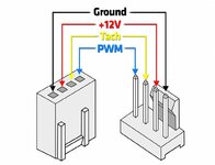
- At the moment the fans are still missing in the drawing. My original plan was to connect 2 of the 4 "Noctua NF-A20" to a D5 Next. Thanks to the ingenious circuit board from [USER = 314775] @Midium [/ USER] I am now thinking of doing the whole thing clean. In other words, to connect all 4 fans to Midium's circuit board. Then I could split the fan connection that controls all 4 fans: solder ground and 12V to the Molex and only let a D5 Next pump control the Tach and PWM. Would that make sense?
- If the distribution of the fan connection makes sense, is it correct that the fans need + 12V? The specifications of the NF-A20 contain the following: "Operating voltage 12 V" and "Voltage PWM signal 5 V". Assume that they actually need 12V and the PWM cable sends 5V.
- The next questions are more related to the soldering itself. I have no experience so far but will practice a little beforehand and prepare accordingly on YouTube. My first question here is about the panel jacks. I read here that these should also be grounded. How did you do it, did you just insert a short cable from socket to pin? So that's how:
- Or is it better to just solder a cable in the pin and then split the cable? This not only affects ground but also 5V. So that's how:
- If 3 cables are then brought together, as in the second socket picture, is it sufficient to insulate them at the point with shrink tubing or should something extra be added?
- The connections to the pins, do they stay "open" or do you make a shrink tube over the pins after they have been soldered?
[USER = 320127] @ mxj1 [/ USER] Man I am not sure how good your German is. I thought it is easier to share the information here and maybe someone else can profit from it at some point too. Above you can see my current cable plan. I followed your advice with the Hubby7 and think it makes sense so far but please have an extra look at it. Also, I am not certain yet how to power up the fans. If I am not mistaken you send ground and 12v through the Molex cable and only controlled the speed & signal via the Pump?
Would be super nice if you can share your 3D Mount for the Hubby. I will find a shop to print it for me and take the whole project to the next level8th-)
Thank you very much.
Best regards,
your Rapha
")
Man probs to google translate it is pretty spot onYou're getting on well ...
My German is as good as Google's. Without Google you all may as well be speaking German to my English. : D
My idea is to make a harness for the mora. this allows all pieces to be plugged and unplugged individually. This adds extra cost and complexity, but yields to a more serviceable part in my opinion.
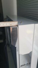
2. I connect the fans by tapping directly into 12v / GND from the socket. This supplies clean, stable power at all times and you don't end up with fans that flutter when starting (one of my D5 Next can only start three fans. The fourth always flickers). I do this by creating two additional four pin male fan sockets to split power and pwm circuits. One socket provides the power and the other socket is connected to a fan cable that goes to one D5 Next with rpm and pwm. When the power is tapped from the neutrik and the rpm / pwm is tapped from the D5 Next, this creates one single socket for all 8 nfa fans to connect to. Maybe this picture of the mora cover will help.
Anhang anzeigen 657967
For 12v / 5v / GND connection I use a 6 pin atx connector because this is a better connector than four pin molex, and the connector is small enough to pass through the hole thats required to be drilled in the mora grill cover. Otherwise, removing the socket would require de-pinning the molex and defeats the easily serviceable aspect that I want. The USB connection also gathers 5v and GND from a splice in the wires after the neutrik socket.
3. You can see above how the fans receive connection. They require 12v and GND from the neutrik socket, and a single RPM and PWM connection from one of your pumps. in the photo above, the single four pin connector with ONLY two wires is the rpm / pwm connection to the D5 Next. You can see how that feeds into the connection with FOUR wires to connect to the fans. You can see that the FOUR wire connector also taps 12v and GND from the ATX connector (which taps the neutrik socket). Below is a photo of the connections on the harness for the mora.
Anhang anzeigen 657970
4. You can ground the neutrik socket exactly how your illustration is drawn. My understanding for this extra wire is just a drain wire for shielding the USB data thats transmitted within the cable. Someone like @ deveth0 surely knows more about this than me though. However, this is not 100% necessary. I would do this if transmitting vulnerable data for some distance, but its hardly required and can be safely overlooked for just a mora project.
9. heat shrinking over the soldered terminals is not required, but does lend to a better finish over all imo. The distances are great enough between pins that there is no chance of arching if done correctly. Also, "don't poke your screwdriver around in there with no insulation."
I've added the bracket to thingiverse . I am new to sharing files so please tell me if there's a problem.
Anhang anzeigen 657999
Also for the quadro friends, I've added it here .


Jeder, der nicht auf einen Drucker zurückgreifen kann, kann sich gerne bei mir melden, gegen einen entsprechenden Obulus kann ich die Teile drucken und verschicken.I've added the bracket to thingiverse . I am new to sharing files so please tell me if there's a problem.
Also for the quadro friends, I've added it here .
Ich nehme dann 1250 Stück bitte.Jeder, der nicht auf einen Drucker zurückgreifen kann, kann sich gerne bei mir melden, gegen einen entsprechenden Obulus kann ich die Teile drucken und verschicken.
haha, dann kannste ja auch schon eine Spritzgussform herstellenIch nehme dann 1250 Stück bitte.

Indeed and agreed, good job sir. Now its much easier and comfortable to use.I often find the translations with deepl.com more readable.
I don't know if I will ever use it, but I want to say thank you for your 3D print files. Great stuff
Siehe oben war ein Scherz, aber du könntest ja mal so ne Pi mal Daumen Rechnung machen, welches Material und was das so kosten müsste+ Obolusse (klingt immernoch so falsch @ShirKhan was hast du mir da angetan^^) von Uns.haha, dann kannste ja auch schon eine Spritzgussform herstellen

Sweet! Ich habe in der Tat keinen Drucker und ein entfernter Bekannter den Ich Uhrsprünglich gefragt habe meldet sich nicht. Ich bräuchte den Hubby7 halter. Müsste halt via Post nach Dänemark aber selbstverständlich würde ich für die Kosten aufkommen. Könnte dir das Geld via bsp. Paypal senden.Jeder, der nicht auf einen Drucker zurückgreifen kann, kann sich gerne bei mir melden, gegen einen entsprechenden Obulus kann ich die Teile drucken und verschicken.
Frag mal @bundymania der hat bestimmt mal beide gegeneinander antreten lassen.Gibt es irgendwo nen Perf.vergleich zwischen einem „airplex GIGANT 3360“ und 2x Mora 420 bzw. 3x Mora 420?
Der airplex liegt ja flächenmäßig bei ca. 2,66x Mora 420…
Ich hatte bestellt, als da stand "verfügbar am xx", was genau 3 tage in der zukunft lag.Hallo Leute,
ich frage mal hier in den Raum, ob jemand auch seit ner gefühlten Ewigkeit auf die Lieferung seines Mo-Ra 420 wartet? Ich habe am 01.07. bestellt und warte immer noch. Watercool sagte eine Charge musste wegen Fehlproduktion weggeworfen werden, aber wie lange kann das bitte dauern?
Indeed, I do have a modular PSU. I was actually already thinking about doing this and I like the idea. Since I already have all the tools and quite some extra cable supply was I thinking to make all cables custom. But this is once the Mora setup is complete (if ever*I would make one more recommendation based on your drawing. I'll presume you have a modular PSU. in that case, do away with your molex four pin connection inside the pc and run your neutrik socket straight back to a male 6 pin atx connector at the psu.
) and I need another project. I really like your powder coated pump setup. It does look very good in black.I have 8 myself, but all are at the same speed... The minimum speed is more than enough to cool my 600 watts.Ask around: some of you definitely have push / pull with the A20s.
Now I had read that in such a fan configuration different fan speeds would be possible. Depending on the source, either the push or the pull fan is faster.
How did you handle that? Different speeds and if so, which ones?
Einfach nur 4 Stück mit 50% rpm und gut ist, wenn du mehr power willst kauf dir z.B. Arctic P14 oder kleinere Noctua und dreh die voll auf. Ist dann etwa die Lautstärke von p/l bei den 200er damit es effektiv was bringt.Frage in die Runde: einige von euch haben ja bestimmt Push/Pull mit den A20s.
Jetzt hatte ich gelesen, dass sich in so einer Lüfterkonfiguration unterschiedliche Lüftergeschwindigkeiten anbieten würden. Je nach Quelle entweder die Push oder die Pull Lüfter schneller.
Wie habt ihr das gehandhabt? Unterschiedliche Geschwindigkeiten und falls ja, welche?
Frage in die Runde: einige von euch haben ja bestimmt Push/Pull mit den A20s.
Jetzt hatte ich gelesen, dass sich in so einer Lüfterkonfiguration unterschiedliche Lüftergeschwindigkeiten anbieten würden. Je nach Quelle entweder die Push oder die Pull Lüfter schneller.
Wie habt ihr das gehandhabt? Unterschiedliche Geschwindigkeiten und falls ja, welche?
Jo, sehe ich ähnlich, meine 4 Chromax laufen auch nur auf 20%. Aber 30 Grad Wassertemp dürfen die langsam aufdrehenEinfach nur 4 Stück mit 50% rpm und gut ist, wenn du mehr power willst kauf dir z.B. Arctic P14 oder kleinere Noctua und dreh die voll auf. Ist dann etwa die LAutstärke von p/l bei den 200er damit es effektiv was bringt.

Wobei dann wieder im raum steht, ob das noch effektiv genutzt werden kann... irgendwann ist man halt am limitHab letztens einen gebrauchten MoRa 3 360 mit 180er-Lüftern gekauft. Da hat einer fast 16W - also zusammen mehr als 60W Lüfter-Leistung 😳 Echt krank, wie die pusten