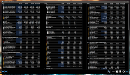
[Sammelthread] Intel DDR5 RAM OC Thread

@Veii whats the difference between fixed vcore + LLC at static clocks vs default dynamic clocks and auto voltage in terms of ram OC. How does auto voltage help RAM? Like if I used a low acll for undervolt how is that better than manual core + LLC?
Low IA_AC_LL is not better.
Fixed voltage is bad when it comes to the lifetime of the CPU, because you break VIDs voltage-assignment and loadassignment.
You cant have a curve when you break its dynamicness by constant supply.
No curve = misbehaving core, ring, cache clock and remain internal clocks.

It was written here recently again :)
VID & IVR are dynamic supplies, based on load, guardbands and priority.
Your memory voltages all are also delivered from/as LDO's.

Without curve work no prioritizing will change.
But with supply cutting you extrapolate the problem of low supply.

VDD2_CPU is not VDDCR_IA
VDDCR_SA is not IMC
MC-Link VDD(2), Data rail
And MC-Link VDDQ_CPU Data-Voltage rail
Are not IMC voltages.
They are transition voltages, going from each MC-LINK -> through PCB -> to mem slots.
Where when they arrive, are synced by already on-memory VDD_MEM & VDDQ_MEM.

Because those two voltages on CPU side are very far away of the memory, they are amplified.
Which means that amperage matching + loss, is done.
Voltage itself, its level means herby zero.

If you want more margins for voltage management inside CPU, you have to work with the curves.
Not linearly use an exploit and drop voltage before it even arrives to the CPU.
 
Zuletzt bearbeitet:
Wenn Du diese Anzeige nicht sehen willst, registriere Dich und/oder logge Dich ein.

Anhänge

  • Super_PI_32M_302.019.jpg
    Super_PI_32M_302.019.jpg
    506,1 KB · Aufrufe: 72
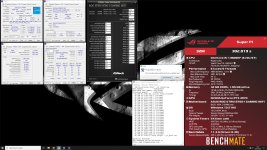
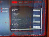
Hab meine 7800er von Computer-Republik jetzt zu 8200 überreden können.
Die Spannungen sind vielleicht noch etwas zu viel des Guten 😁
Wenigstens habe ich da ein XMP Profl bei dem ich nach einem missglückten Versuch nicht wieder alles neu eintippen darf.
 

Anhänge

  • IMG_20240216_215326.jpg
    IMG_20240216_215326.jpg
    1,7 MB · Aufrufe: 77
  • 02-16-2024-21-41-00.png
    02-16-2024-21-41-00.png
    336,9 KB · Aufrufe: 74
auch das ist mir ein begriff 🥲
passenderweise neu in der Sammlung:

WhatsApp Image 2024-02-16 at 22.17.55.jpeg
 
Black Apex, White APEX
Encore's PCB has different characteristics :)

RTTs on DIMM may work due to Groups
But Groups & RONs are on CPUs side.
So that means through board.

This also means that they can never be tansferable to all ASUS boards or all 1DPC
Groups are an interesting kind, but its still ODT from Mem Controller through PCB to mem slot.

CTL (0,1,2) uses VDDQ as base
RON use VDDQ as base
More hidden timings do that when building VREF
and then RTT controls access to ICs , subchannels and bankgroups based on what it receives. A differential signal.

There is unfortunately no way how you can reuse that data. But maybe the meaning of information can be transfered.
As for the rest of the Post, its too many questions to answer right now.

Disable VDDQ Training and start to look for your actual voltage target.
Update to bios 0081 , remove all PLLs and probably move near 170mV delta between VDDQ_CPU to VDDQ_MEM
Keep VDD2 bellow and max equal to VDD_MEM. Keep VDDQ_CPU min-equal or above SA.

Don't use strong IA_AC_LL as that will limit maximum range of IMC.
All is loadaware and voltage sheduled. Nearly all voltages are either VID or IVR. Aka loadblanced.
Cutting supply is harming all of them together.
Making more margins by working with V/F curve an undervolting cores ~ is the way to go. No supply cutting
Hi @Veii, how are you? When I created this account I put my nickname wrong, which is one I use in games! I am @lmfodor. I'll see if I can change it. You have helped me a lot in the other forum, and in fact with my 13700k I used your BIOS config file, including your AC/DC_LL and your VF offsets. I must say that they worked very well for both the processor and the 7200. In fact, I always disabled VDDQ Training, but when changing processors I encountered some limitations. First, because of how ASUS handles the SVID, if I leave it in "Let BIOS Optimize" I see that it sets PL1 to 253W and PL2 uncapped. If I select "Disabled Enforce all limits, it uses Intel's limits at 253W, so the processor reaches 55/56x in the Pcores, not bad for YC tests. But if I activate ""Enable - Enforce All limits" there I should define the AC/DC so that it works properly. I mean, I would like to achieve än optimal CPU performance without a strong OC, I don't need 6.x, just for it to work with the best performance / consumption / temps ratio and that leaves headroom for a good OC of mems.

Regarding the RONs, yes, I have read a lot about your posts and I have achieved a good delta at low speeds (7200), however now, for example for 8200 with a kit from 8000 to 1.45, I see that 1.48v VDDQ is the lowest value to pass YC. Then TX left it in Auto, but when for example I set it to 1.3v or 1.31/2v, I couldn't make it stable. On the other hand , I see that my SA values are high, well 1.28 is not that high, but I did notice that in many Apex they manage to be below 1.2, which surprises me.

Regarding my V/F curve, I understand that it is not a "leaked?" curve. I'd like to first be able to configure the processor well so that it works well and leaves room to continue with the memory OC, which I think could greatly improve signal integrity. Regarding the CTLs, I managed to read all the trained parameters with RU, but I continue using as input the values that you indicated as a reference for DQVrefUp/Down. In fact, I wanted to see if I could read the RTT, if for example I put similar values and then look in the BIOS to find out how it trains.

Now, I'm using everything on AUTO, because I want to configure this processor well. I'm reading your V/F curve post, it's not something I've mastered yet. Does it make sense that for example I set my DC_LL to the value I found, where SVID=Vcore=VRM Vcore? Regarding AC_LL, I couldn't download it, now it is on auto, but I would try the value that OCTool reads for LLC4, what do you think? And about my V/F curve, which seems good, could I adjust selecting a negative offset starting at line 7?

Screenshot 2024-02-16 200124.png

Screenshot 2024-02-16 200527.png


14900K VF Curve.jpg
I don't know if it makes sense to correct the curve at the bottom, but if the slope, perhaps from V/F 7, trying with (-) 0.005 would take me to 1.269 for 56x and 1.304 for 5.8. Would this be a good starting point to try?
It's a pleasure to be in contact with you again! Thanks, as always @Veii
 
Zuletzt bearbeitet:
Low IA_AC_LL is not better.
Fixed voltage is bad when it comes to the lifetime of the CPU, because you break VIDs voltage-assignment and loadassignment.
You cant have a curve when you break its dynamicness by constant supply.
No curve = misbehaving core, ring, cache clock and remain internal clocks.

It was written here recently again :)
VID & IVR are dynamic supplies, based on load, guardbands and priority.
Your memory voltages all are also delivered from/as LDO's.

Without curve work no prioritizing will change.
But with supply cutting you extrapolate the problem of low supply.

VDD2_CPU is not VDDCR_IA
VDDCR_SA is not IMC
MC-Link VDD(2), Data rail
And MC-Link VDDQ_CPU Data-Voltage rail
Are not IMC voltages.
They are transition voltages, going from each MC-LINK -> through PCB -> to mem slots.
Where when they arrive, are synced by already on-memory VDD_MEM & VDDQ_MEM.

Because those two voltages on CPU side are very far away of the memory, they are amplified.
Which means that amperage matching + loss, is done.
Voltage itself, its level means herby zero.

If you want more margins for voltage management inside CPU, you have to work with the curves.
Not linearly use an exploit and drop voltage before it even arrives to the CPU.
Hello,
For now I've set 6.0-5.4/4.2 with completely auto voltages and LLC 3. I set acll 0.11 and dcll 1.1(as per mohm table). What should I do next? I went a fair bit back reading all your posts yesterday but I haven't been able to figure what you mean by "tune your curve". Appreciate your help!
 
Hello,
For now I've set 6.0-5.4/4.2 with completely auto voltages and LLC 3. I set acll 0.11 and dcll 1.1(as per mohm table). What should I do next? I went a fair bit back reading all your posts yesterday but I haven't been able to figure what you mean by "tune your curve". Appreciate your help!
Do not fix clock~~
Do not fix cpu voltages~
Both will mess with DynamicVFS.
In this case its rather AdaptiveVFS ~ similar to AMDs. But maybe Intel™ has a new name for it now.
12th gen was dynamic with own volt/freq points. 13/14th gen onwards is Adaptive with curve shape and interpolation.
Highest voltage win's approach. With "shape" defining ramp "time". Well ramp amount, very similar thing.

Ring auto adjusts based on load and load difficulty. Ring V/F is build on core v/f. Underlaying and inspired, not used or controlled by.
Cores adjust based on VID. UncoreVID adjusts based on cores and extra's.
Everything is connected. Do not force constant clock, else you override dynamicness

V/F curve
The one that is shown if you have an asus board under Voltage-Frequency Points.
Those 11 points, with the help of Shamino (ASUS) WorkTool (OC-Pack).

You stay at ~0.60-0.65ohm IA_AC LL and undervolt with the curve.
DC_LL you keep auto.
Default is at 0.55, but for high clock its give and take. For normal users 0.55 is plenty.
We build our curve on 0.62-0.65. And then cut supply on cores side. To leave more margins for higher strain and offset internal VID (package) throttle.
 
Zuletzt bearbeitet:
Do not fix clock~~
Do not fix cpu voltages~
Both will mess with DynamicVFS.
In this case its rather AdaptiveVFS ~ similar to AMDs. But maybe Intel™ has a new name for it now.
12th gen was dynamic with own volt/freq points. 13/14th gen onwards is Adaptive with curve shape and interpolation.
Highest voltage win's approach. With "shape" defining ramp "time". Well ramp amount, very similar thing.

Ring auto adjusts based on load and load difficulty
Cores adjust based on VID. UncoreVID adjusts based on cores an extra's.
Everything is connected. Do not force constant clock, else you override dynamicness

V/F curve
The one that is shown if you have an asus board under Voltage-Frequency Points.
Those 11 points, with the help of Shamino (ASUS) WorkTool (OC-Pack).
I just used by core usage and set 2x60 and 8x 54, is that also forcing constant clocks? How else can I run lower clocks
 
I just used by core usage and set 2x60 and 8x 54, is that also forcing constant clocks? How else can I run lower clocks
Ah ?
Just TVB.

Capping max clocks is not forcing constant clock :)
But fixing multipliers = OC Mode for the CPU and that breaks dynamicness + throttle ability = damage.

The curve you build is based on the fused curve in the CPU
Intels SVID presets are an extensions of it.
Better to make your own~

The curve will automatically extend till target clock
Messing with max clock limiters is not going to change curve shape, but may change cpu stability or instability.
TVB extension should not be used till memory is stable.
But curve tuning should be done before one messes with mem.

Later you just scale up and down IA_AC, when high clock may need more IA supply.
Messing with that value is a linear shift up and down.
But curve is never linear to begin with. Soo first, is shaping curve at X IA_AC value.
Then later its easier to shift it up and down without having to redo whole curve.
I'm idling at 0.5V now, after leaving ring auto and just setting x8-54 and ecores auto. So how can I make my own curve, I've always used fixed vcore so I don't know about the tvb settings
 
I'm idling at 0.5V now, after leaving ring auto and just setting x8-54 and ecores auto. So how can I make my own curve, I've always used fixed vcore so I don't know about the tvb settings
ASUS WorkTool
Read back some pages.
https://www.hardwareluxx.de/communi...-ram-oc-thread.1306827/page-445#post-30274486 has a spoiler with some of the old threads that lead you 55-60 pages back
From then you can read till here :')

In all seriousness, its a too big topic to rewrite the 4th time.
The talk with zebra_hun and tibcsi
GL :)

I know the posts are a lot
But, it is what it is. Difficult topic.
Visually it is better but i work with what i have now~
I guess its better than nothing, and especially it being freely readable instead of paywalling it or keeping it for myself. 🤭
 
What should tXSR be set to for 8,000 mt/s? I read that tXSR = tRFCpb to not cross talk. Is this still true? I'm trying to dial in 2x24GB kit.

tRFC 672
tRFCpb 546
 
ASUS WorkTool
Read back some pages.
https://www.hardwareluxx.de/communi...-ram-oc-thread.1306827/page-445#post-30274486 has a spoiler with some of the old threads that lead you 55-60 pages back
From then you can read till here :')

In all seriousness, its a too big topic to rewrite the 4th time.
The talk with zebra_hun and tibcsi
GL :)

I know the posts are a lot
But, it is what it is. Difficult topic.
Visually it is better but i work with what i have now~
I guess its better than nothing, and especially it being freely readable instead of paywalling it or keeping it for myself. 🤭
So VT3 runs normally at 1.17V die sense but SFT is running much lower clocks. Should I set avx offset to 0? I don't know what's going on here
 
So VT3 runs normally at 1.17V die sense but SFT is running much lower clocks. Should I set avx offset to 0? I don't know what's going on here
ICCMAX set ?
Electrical limitations hit
Or PL1/2 limitations hit.

Most likely ICCMAX hit + internal peak-VID throttle.

VRMAX to 1550
ICCMAX to 400A for 14900K
364A for 14700K. If not 320A plus requiring you to manually work on V/F points.

EDIT:
If not power or electrical limited
if not VID limited
Its called strain throttle, which is perfectly normal
AVX2 loads have a fixed offset for voltage and clock - guardbands.
But clock means nothing, it depends internally what causes the limit.

Also one AVX2 load, means not the VID on another AVX2 load.
When you understand why, you will understand how bad fixed clock or voltage actually is.

EDIT2:
Things you want to test and note when working on curve
1708127904514.png

Add CB R15 Extr to the mix
But you will quite fast notice that clock means nothing & effective clock becoming irrelevant.
 
Zuletzt bearbeitet:
ICCMAX set ?
Electrical limitations hit
Or PL1/2 limitations hit.

Most likely ICCMAX hit + internal peak-VID throttle.

VRMAX to 1550
ICCMAX to 400A for 14900K
364A for 14700K. If not 320A plus requiring you to manually work on V/F points.

EDIT:
If not power or electrical limited
if not VID limited
Its called strain throttle, which is perfectly normal
AVX2 loads have a fixed offset for voltage and clock - guardbands.
But clock means nothing, it depends internally what causes the limit.

Also one AVX2 load, means not the VID on another AVX2 load.
When you understand why, you will understand how bad fixed clock or voltage actually is.

EDIT2:
Things you want to test and note when working on curve
Anhang anzeigen 971851
Add CB R15 Extr to the mix
But you will quite fast notice that clock means nothing & effective clock becoming irrelevant.
this is what im running rn its all auto with ACLL 0.15 and all limits removed + 400A iccmax. thoughts?
1708148069006.png
 
What should tXSR be set to for 8,000 mt/s? I read that tXSR = tRFCpb to not cross talk. Is this still true? I'm trying to dial in 2x24GB kit.

tRFC 672
tRFCpb 546
Old story.
672 = 711 XSR
It needs to be over RFC + x delay.
Its my own formula :)
Beitrag automatisch zusammengeführt:

this is what im running rn its all auto with ACLL 0.15 and all limits removed + 400A iccmax. thoughts?
Anhang anzeigen 971878
Hover with the mouse over the electrical design point limit an tell me what it says :)
ICCMAX captures many things.

Either curve VID throttle, or IMC throttle :)
Up to clock you may expect 1.3-1.4 10^10

Soo no way around undervolting, haha.
You can cut input, but if you dont actually undervolt the right way ~ you package throttle
I hope this was a clear enough visualization for you.

Soo that also means if IMC throttles too much, it will simply crash~
As all voltages are dynamic and load balanced.
 
Zuletzt bearbeitet:
Old story.
672 = 711 XSR
It needs to be over RFC + x delay.
Its my own formula :)
Beitrag automatisch zusammengeführt:


Hover with the mouse over the electrical design point limit an tell me what it says :)
ICCMAX captures many things.

Either curve VID throttle, or IMC throttle :)
Up to clock you may expect 1.3-1.4 10^10

Soo no way around undervolting, haha.
You can cut input, but if you dont actually undervolt the right way ~ you package throttle
I hope this was a clear enough visualization for you.

Soo that also means if IMC throttles too much, it will simply crash~
As all voltages are dynamic and load balanced.
this is all it says.
1708133365227.png

Beitrag automatisch zusammengeführt:

also since we are talking clocks i have high perf powrplan right now, should i switch to balanced?
 
Zuletzt bearbeitet:
this is all it says.
Anhang anzeigen 971916
Beitrag automatisch zusammengeführt:

also since we are talking clocks i have high perf powrplan right now, should i switch to balanced?
1708136269996.png

Potentially yes
This is what it limits, partially.

Soo this includes nearly all voltages.
No undervolt, no memOC
 
ICCMAX set ?
Electrical limitations hit
Or PL1/2 limitations hit.

Most likely ICCMAX hit + internal peak-VID throttle.

VRMAX to 1550
ICCMAX to 400A for 14900K
364A for 14700K. If not 320A plus requiring you to manually work on V/F points.

EDIT:
If not power or electrical limited
if not VID limited
Its called strain throttle, which is perfectly normal
AVX2 loads have a fixed offset for voltage and clock - guardbands.
But clock means nothing, it depends internally what causes the limit.

Also one AVX2 load, means not the VID on another AVX2 load.
When you understand why, you will understand how bad fixed clock or voltage actually is.

EDIT2:
Things you want to test and note when working on curve
Anhang anzeigen 971851
Add CB R15 Extr to the mix
But you will quite fast notice that clock means nothing & effective clock becoming irrelevant.
Hi @Veii,
I had read about setting VCCMAX to 420 but I see that in your previous posts you recommend leaving it at 400A. I'm going to start there, should I leave the Enabled - Enforce All Limits option then? SVID in trained and I had just set VRMAX to 1550. I'm going to try some offsets with the OC Tool to see if I can improve my curve, excellent post BTW! I have something to entertain myself during the week :-). An additional question, when you had sent me your BIOS configuration for 7200 you had defined for your CPU the following:

CPU Input Voltage Load-line Calibration [Auto]
CPU Load-line Calibration [Level 4:Recommended for OC]
Synch ACDC Loadline with VRM Loadline [Enabled]
CPU Current Capability [120%]
Maximum CPU Core Temperature [105]
Package Temperature Threshold [100]
IA AC Load Line [0.35]
IA DC Load Line [1.30]

Although for now Im not going to configure the IA AC/DC_LL to properly set the V/F Curve, do you know if the Synch ADCDLL with VRM option overwrites the values that one defines? I thought it should be left disabled. On the other hand, what would be the objective of defining a Max Core Temp at 105 and a Package at 100? These AC/DC_LL worked perfectly for me on my 13900k. But you have saved me with my 7200 configuration, with the Hero it was very difficult to stabilize it. Thank you!
 
Zuletzt bearbeitet:
Guten Morgen.

Ich habe da mal zwei fragen :

Nr. 1 Welches ist Aktuell bei Euch das stabilste Bios für das Apex (nicht Encore) in verbindung mit der 14.Gen?

Frage Nr. 2 woraus setzt sich nochmal tWR zusammen? tWRpre +? .

Hintergrund ist das ich sporadisch fehler 55 habe und habe eigentlich keine sonderlich scharfen Timings .Sobald ich tRefi auf 65535 setze kommt sporadisch der fehler beim Starten oder reboot.
Mit 32767 ist es Besser.

Aktuell habe ich Bios 1801.

Apex.PNG

SA 1,168V , VddqTx 1,35V , IMCVdd 1,35V , VDD/VDDQ 1,45V

Danke für Eure Tips
 
kleines Update:
vdd 1.55
imc und ivr beide auf 1.35.
sa 1.21
TM5 error bei 15min, siehe Bild. Was bedeutet nun dieses Errors?
Timings gleich, wie letztes Post.

Edit: mit 1.56vdd, rest gleich, ein Freeze bei 34min.
 

Anhänge

  • error tm5.png
    error tm5.png
    358,5 KB · Aufrufe: 55
Zuletzt bearbeitet:
next step? now that clocks are fine
We see the limit :)
We see you will not get anywhere with telemetry spoofing.

Its time to stop using IA_AC exploit , of tuning board to be reported as high leaky low quality type.
And start to actually tune VID and let it internally assign voltage.

You will not get any further with this cutting-supply exploit.
Spend the day(s) learning how to work with CPUs algo.
Translate some pages from germn into english. And i guess the major rest is already in english, soo it shouldnt be too much work.

AC_IA 0.65 as foundation and build/undervolt your curve.
Till you dont reach that ICCMAX limiter anymore.
CPU will thank you :-)

No going around limiter, else you trade in sample health. It already limits your memOC and raw compute ability, till you keep staying under the limiter.
No way of going around the problem of undervolted cores.
But VIDs need to stay high if needed or low on harsh workload.

Best of luck.
Its not that hard, and generally it was time to stop with fixed clock. We are not in skylake days anymore.
This powerdraw/loadline exploit also very likely will not work on new CPUs. Its lucky to even work on 13/14th gen.
Better learn the CPU instead of working against it :giggle:

EDIT:
In the current moment, this is the way to give you help.
Sorry that its much to read, but it is what it is.
When someday there are sponsors, then i can illustrate better & not rely on old scattered data. :)
Currently thats the way~
Sorry.
 
Zuletzt bearbeitet:
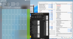
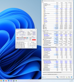
Mal ein guter Versuch. Tm5 und Karhu kann ich grad noch nicht laufen lassen, da noch passiv gekühlt wird und ich noch keine Lösung habe. Ein paar Tests laufen schonmal.
Teste dann noch Gaming.

8000.png8000 volt.PNG
8000 C36 1.png
Y 2.5 8000.PNG

Ist doch ganz Ok bisher oder?
 
Sieht nach "Tweaked XMP" aus. :unsure: VDD und VDDQ kannst du wahrscheinlich noch senken.
 
Sieht nach "Tweaked XMP" aus. :unsure: VDD und VDDQ kannst du wahrscheinlich noch senken.
Es ist XMP1 , nur tWR und tRefi angepasst.
Die Funktion Tweaked XMP kenne ich vom Z790 Strix-F , jedoch habe ich die hier garnicht zur verfügung oder muß bei diesem Board Ai OC per F11 aktiviert werden?
MCH Full ist an, MRC Fastboot off, Round trip latency an.
Ich kann probieren VDD/VDDQ zu senken, aber meine CPU hat nur einen MC SP von 61. Ich probiere es dennoch mal.

8200 C38.png

Zumindest funktioniert 8200 C38 bei gleicher Spannung Bench stable. Y-Cruncher 2.5 kommt das berüchtigte Coiffizient too large ^^
 
Es ist XMP1 , nur tWR und tRefi angepasst.
Die Funktion Tweaked XMP kenne ich vom Z790 Strix-F , jedoch habe ich die hier garnicht zur verfügung oder muß bei diesem Board Ai OC per F11 aktiviert werden?
MCH Full ist an, MRC Fastboot off, Round trip latency an.
Ich kann probieren VDD/VDDQ zu senken, aber meine CPU hat nur einen MC SP von 61. Ich probiere es dennoch mal.

Anhang anzeigen 972046

Zumindest funktioniert 8200 C38 bei gleicher Spannung Bench stable. Y-Cruncher 2.5 kommt das berüchtigte Coiffizient too large ^^
Lass dich nicht von der MC SP irritieren, die wird wohl nicht korrekt berechnet.
 
Hardwareluxx setzt keine externen Werbe- und Tracking-Cookies ein. Auf unserer Webseite finden Sie nur noch Cookies nach berechtigtem Interesse (Art. 6 Abs. 1 Satz 1 lit. f DSGVO) oder eigene funktionelle Cookies. Durch die Nutzung unserer Webseite erklären Sie sich damit einverstanden, dass wir diese Cookies setzen. Mehr Informationen und Möglichkeiten zur Einstellung unserer Cookies finden Sie in unserer Datenschutzerklärung.


Zurück
Oben Unten refresh