Veii
Enthusiast
- Mitglied seit
- 31.05.2018
- Beiträge
- 1.486
- Desktop System
- QA Platform
- Laptop
- ASUS 13" ZenBook OLED [5600U]
- Details zu meinem Desktop
- Prozessor
- Intel Core Ultra 9 285K
- Mainboard
- ASRock OC Formula
- Kühler
- Alphacool T38 280mm
- Speicher
- G.Skill Z5 CK 9600
- Grafikprozessor
- GTX1080ti KP [XOC ROM] // EVGA GTX 650 1GB [UEFI GOP]
- Display
- KOORUI GN10 miniLED
- SSD
- Samsung EVO 850
- Soundkarte
- ESI Ambier i1 & AKG P820
- Gehäuse
- Open-Bench
- Netzteil
- Corsair SF85 // Seasonic GX-550
- Keyboard
- Topre Realforce 108UBK 30g [Silenced]
- Mouse
- Endgame-Gear OP1 8K
- Betriebssystem
- Win11
- Internet
- ▼42 MBit ▲15 MBit
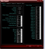
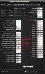
Market MonopolI don't know why those values aren't exposed by ASUS, it's a stupid thing to hide them.
")
Tradesecret
Call it how you want
Intel ecosystem, depends on Boardpartners tuning the Board & community treating it on board-by-board base.
AMD ecosystem, depends on HQ to politely-enforce, tuning which all Boards have to meet. No own ODT/RTT/Timing tuning allowed. Soo AMD is wrong for everything ~ community standpoint 🤭
^ but its kind of easy for the mass, even if fixes take months. All Boards that way are good and behave predicably identical.
If big players leak their FW Tuning, then outside of the PCB which is not thaat variable (all engineers are intelligent, there is no "inferior Boardpartner")
There wont be much of a reason to buy the high end, nor the users pay the price for this tuning.
Then a small STRIX ITX board, wouldnt be tooo much different from a ROG series Board.
A TUF series might, as they consider it entry. But a ProArt or Strix wouldn't be mass-quality.
It wouldnt be practical to outsource another Batch or even Manufacture of the PCBs, just soo quality can be lower.
And if PCB material doesn't change, routing maybe designs some other team ~ it wouldn't be tooo much different.
Its mostly Firmware that limits the lower tier Boards
As an example
I agree with QC and testers section leaving more OC information for the mass and go-by suggestions, like we researchers do.
But, i understand why things are hidden.
As long as active Team to Community communication exists ~ it should be ok.
And as long as users dont get locked out of important bios options ~ of course 🤭
Beitrag automatisch zusammengeführt:
Given we've researched this, for months.I still need to study the skews, tried to play them with help of @CarSalesman , but it's a harder topic for me atm
I can not suggest
What you need to know is out on OCN.
CTL0 is flawless.
The rest needs understanding of Groups and RTTs. Outside of understanding what CPU voltages do.
Then you can tune CTL1's based on the ODT/RTT foundation.
Skewing delays are complicated.
There are already plenty of options that have no user-understandable names to them but stand for DQ, CA, CS.
You guys also miss 30+ memory tuning options.
All those things have higher priority, before you should consider learning about slopes.
Slopes can be calculated, kind of. RTTs (A) power can be calculated ~ kind of.
But ~not wanting to be selfish~.
I strongly don't recommend to waste time there.
Use whats out and work with Boardpartners People, to help bring bios forward.
// The userbase mass tuning and posting is helpful. The selfish research like me who then is annoying, is rather a burden.
All those options shouldn't be userbase's worry. The board has to "just work".
Its what you pay a premium too.
Invest time to understand DQ+CK, CA, CS & DQS
That helps managing some voltages and groups.
This has the highest priority ~ in what i would recommend
Or even if you don't
Look up some papers on the Groups a bit.
This makes more sense for the time invested.
Slopes , they have to be correct to begin with~
Not userbase's work but glad access is given.
Beitrag automatisch zusammengeführt:
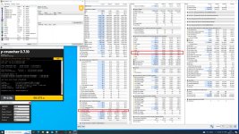
You need to slightly work on thisThere is a small jump in my curve, but still, it looks solid. AC_LL is 0.60 now, I will lower it again to see if it stable on 0.50-0.56

But thank you for the mention and post
I need the floor to be near flat
I wish for a droop bellow 3600MHz
A drop between 4200 to 5200MHz
And a linear spiky peak.
^ goals.
Min near 700mV for safety.
This is what i want to see

You can forward stuff i dont mind~~
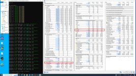
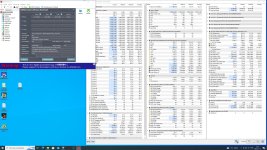
Maybe if you are bored , try to optimise sub 3600MHz section a bit more
use steps of 3mV, and max steps of 6mV. Well 6.25, but tool already does the calculations
Work probably is to make a big drop on P4, let it fix the others
Then make like a 12mV increase in P5 , let it fix the ones
and then add a bump of whatever voltage is left after P2 so it fixes P1 too and is a flat line
That should hopefully create this shape i want to see.
Substrate are not scaling linear !
I'm afraid people on OCN will misunderstand intentions, and think i'm making linear curve * haha.
Curve should be S like. Similar to ASUS Tuning but stronger drop bellow 3600MHz. Subtle droop bellow 5Ghz
Generally only work left is P5 and lower ~ but you need to track game min/avg fps with it. On dynamic jumping load.
* Only AC_LL scales linear.
Zuletzt bearbeitet:


")