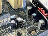
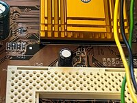
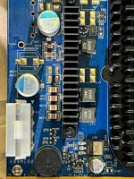
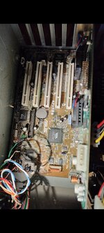
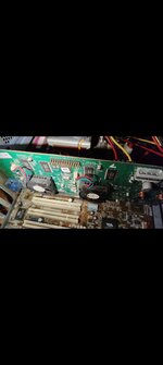
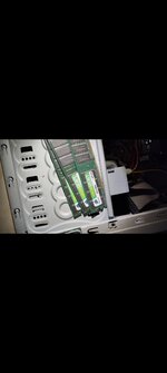
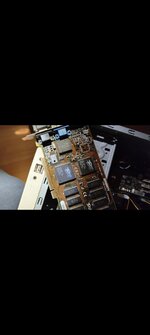
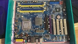
1. Filing empty capacitor spaces on MB to improve stability is a good idea? if yes which i should choose for the VRM, DDR, and PCIe/AGP section, i saw a modded 4coredual-sata2 with the caps filled (red squares)
That's not an easy answer really as it depends on a lot of different factors. You always have to ask yourself two things... a) what total capacity am I trying to replace and b) what is the effective total ESR I'm getting at the end.
If you take the six RLX caps for example, they provide a total capacity of 9.000µF which is already more capacity than what Intels VRM design guide recommends:
So in terms of capacity, I'd say there's already more than enough on that board. Which brings us to ESR...
The more caps you add to the VRM circuit, the more you're lowering the ESR. As you can see in the diagram above, ten 7 mOhm caps give an effective ESR of just 0.7 mOhms which is already quite low. So let's say you bring in another four caps, you then lower the ESR down to 0.5 mOhms in total, which is roughly a 30% decrease in ESR . While it sometimes can have beneficial effects to lower the ESR, it can also have negative effects on the circuit. You always have to keep that in mind because on some boards, a too low ESR causes problems and more instability rather than stability or you might just fry some fets.
So looking at your board, the only reason to add additional caps is to lower the ESR which at 6x 21 mOms would be a whopping 3,5 mOhms effectively, which is quite a bit off the design guide lines.
But if you're replacing the caps anyway, you can easily fix this by using fast caps.
Looking at the VCore caps, you could use something really fast like this:
ESR5, yay! So even with only placing the six caps, you're down from 3,5 mOhms to 0,833 mOhms which is a lot closer to what Intel had in mind. Add one more of those and you're almost spot on, while at the same time staying close to the original capacity.
Of course, if you don't like empty spaces, you could also take 14 of these (they add in some color as well

)
Coming back to your modded example board, I can't quite see what's on there really. The four added ones are Panasonic, no doubt, but no idea what capacity, series and ratings the others are, so I can't really say if that mod makes sense or not but I'd be surprised if that guy wasn't aiming to lower the ESR as well as those caps don't seem like the big 16-20mm high capacity caps. My guess would be anything from 560-820µF.
2. The audio chip works with 3 caps, can I mix the 2 very tiny OST RMH series audio capacitors (can't found DS on internet) with a polymer cap for replace the third bigger one? or i will have problems due to mixing ESR? is more convenient left audio caps (and the tiny OST RMH on mb) withouth touch it ?
NO. Don't do that. When replacing capacitors you always try to aim for a 1:1 replacement – or slightly better – if the circuit this cap sits in allows to do so.
The RMH caps are miniaturized general purpose caps for audio equipment. If you throw an ultra-low-esr polymer cap in there, that's calling for trouble. Replace it with something more suitable in the same capacitor class but not something totally out of line.



 )
)

 entweder ich finde einen mit passendem Ripple aber nicht korrektem Durchmesser oder richtiger ESR aber kein korrekter Ripplestrom.
